Paperless Working Part 1 - GoodNotes

If you were to take a look at my iPad when I’m working I can safely estimate a 90% chance you’d see it running GoodNotes. Everything I would have previously done on paper, is now done on my iPad Pro 12.9” via GoodNotes with the Apple Pencil.

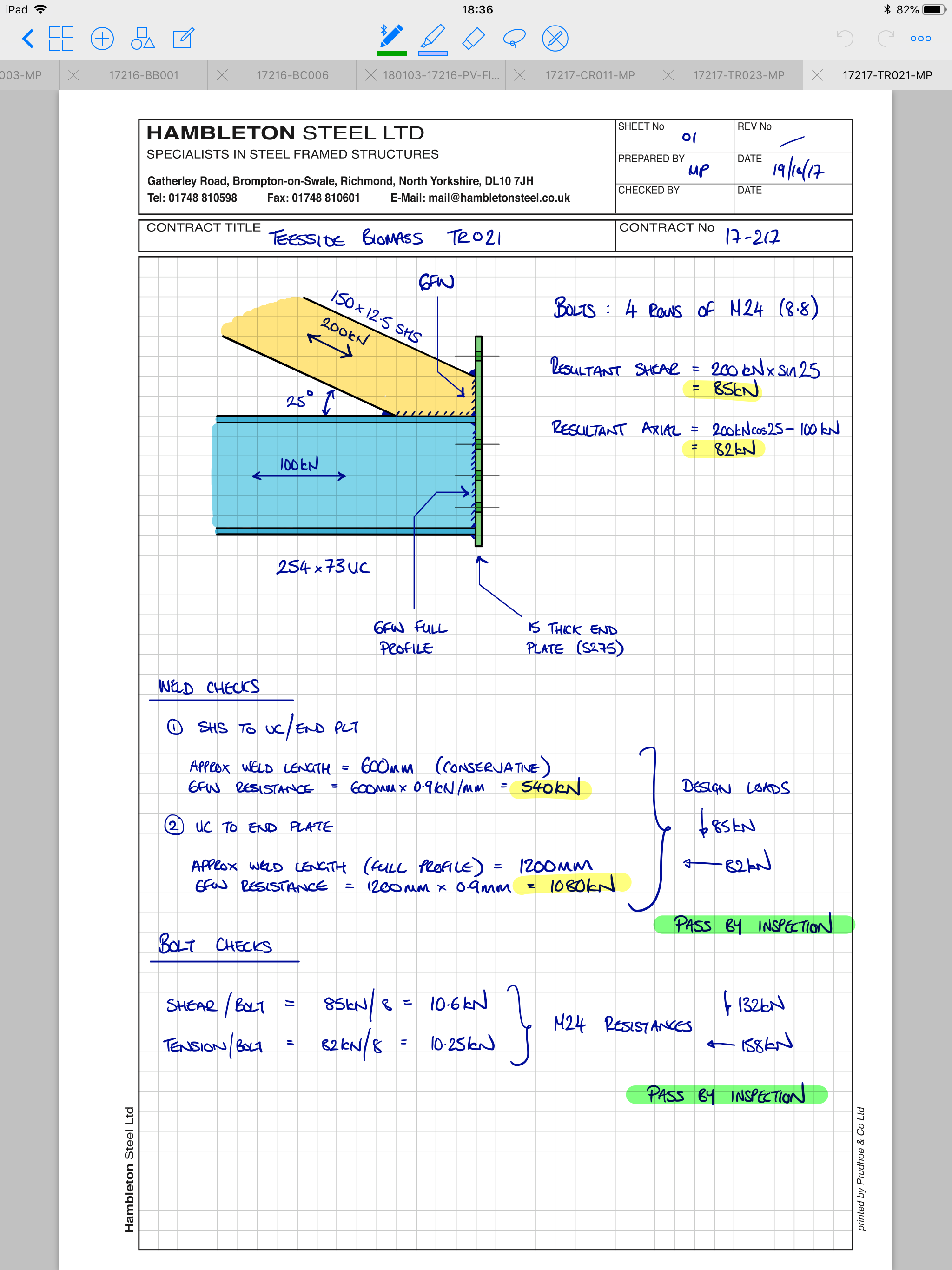
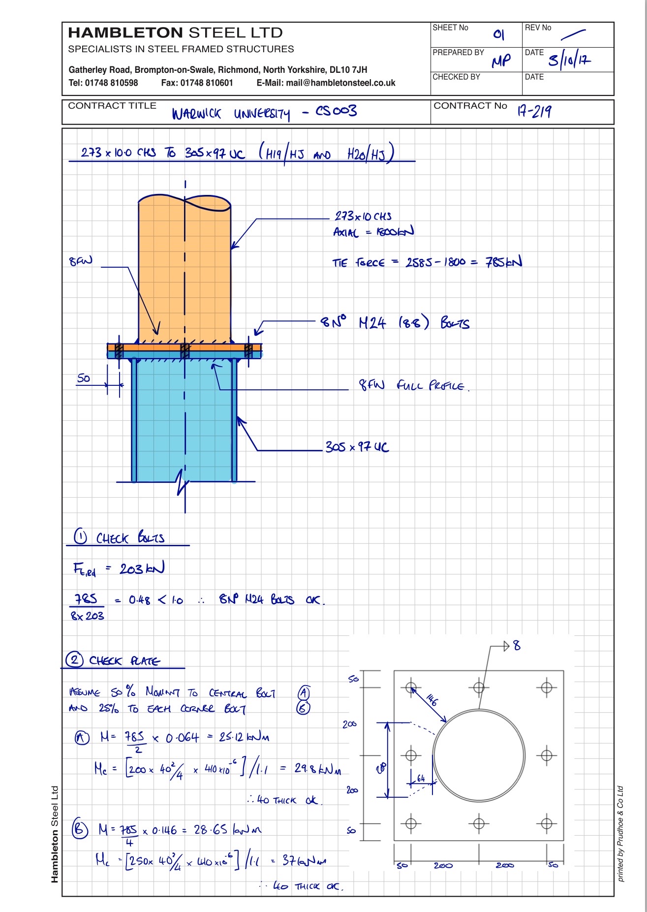
  • Hand calculations: GoodNotes
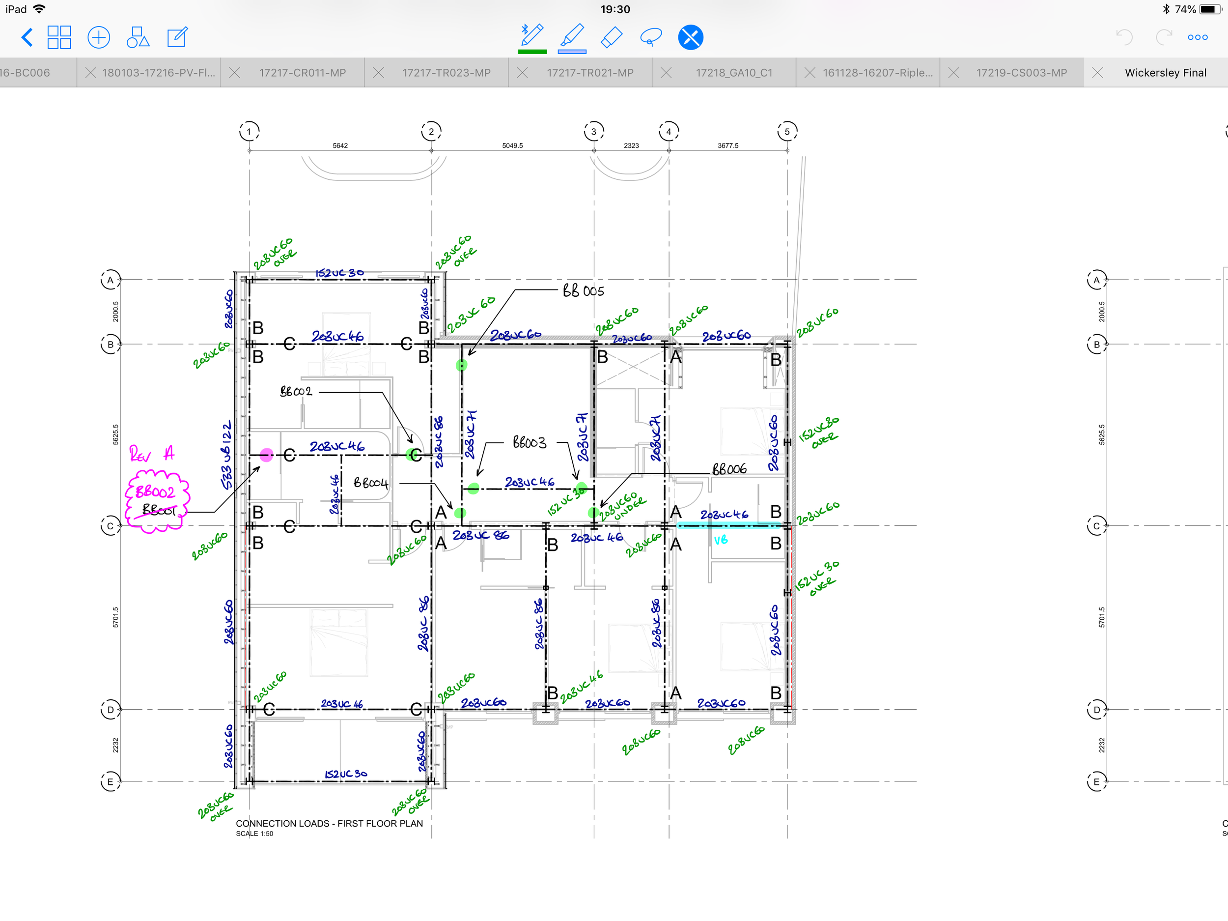
  • Marking up drawings: GoodNotes
  • Any sort of document that requires my signature: GoodNotes
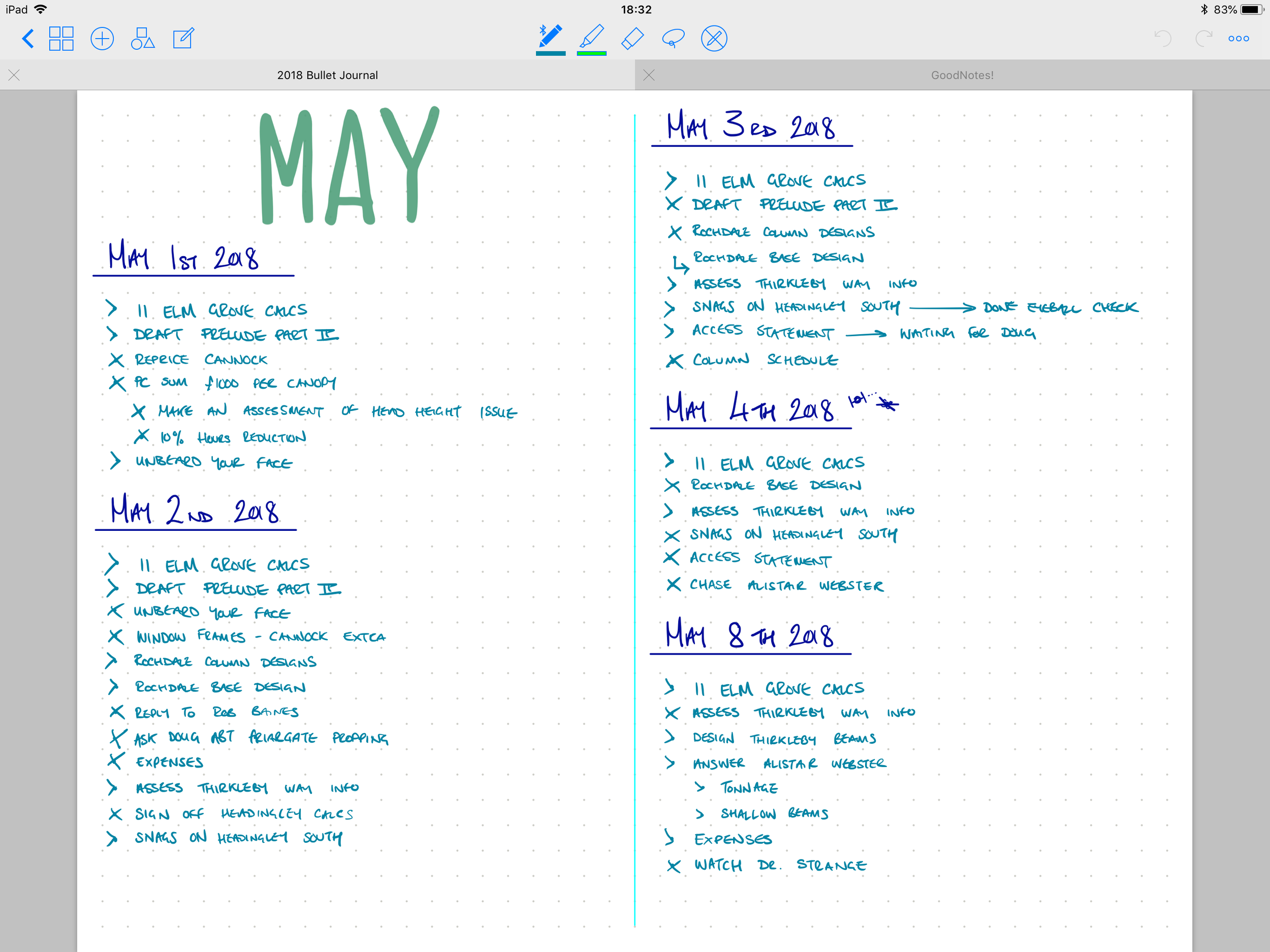
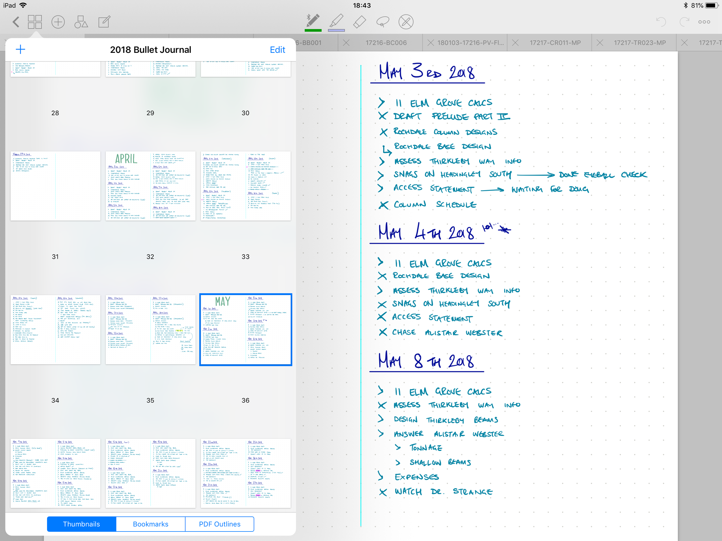
  • To-do list: GoodNotes
  • Specification documents needing to be reviewed: GoodNotes

Note: clicking on an image in the gallery moves to the next image.

And the list goes on. 

GoodNotes is at its core a vector based PDF markup tool with a small but near perfect box of tools. The most notable feature is the very best digital handwriting inking engine I’ve seen on iOS - and I have tried a lot of handwriting apps. The talented people who made and maintain GoodNotes market it heavily to students as a note-taking tool, and with good reason - it is truly wonderful for note-taking. The great news for engineers is that the features included and the design decisions made for GoodNotes make it an incredible paper replacement for the practicing structural engineer.

Before we talk about why GoodNotes is great for engineers, let’s cover the basics: Any handwriting app worthy of notice should feel great to write on, and produce handwriting that is unmistakably that of the writer. GoodNotes does this splendidly. The act of writing feels natural, and the results, at least to my eye, are perfect. Also notable: the palm rejection with the Apple Pencil is great.

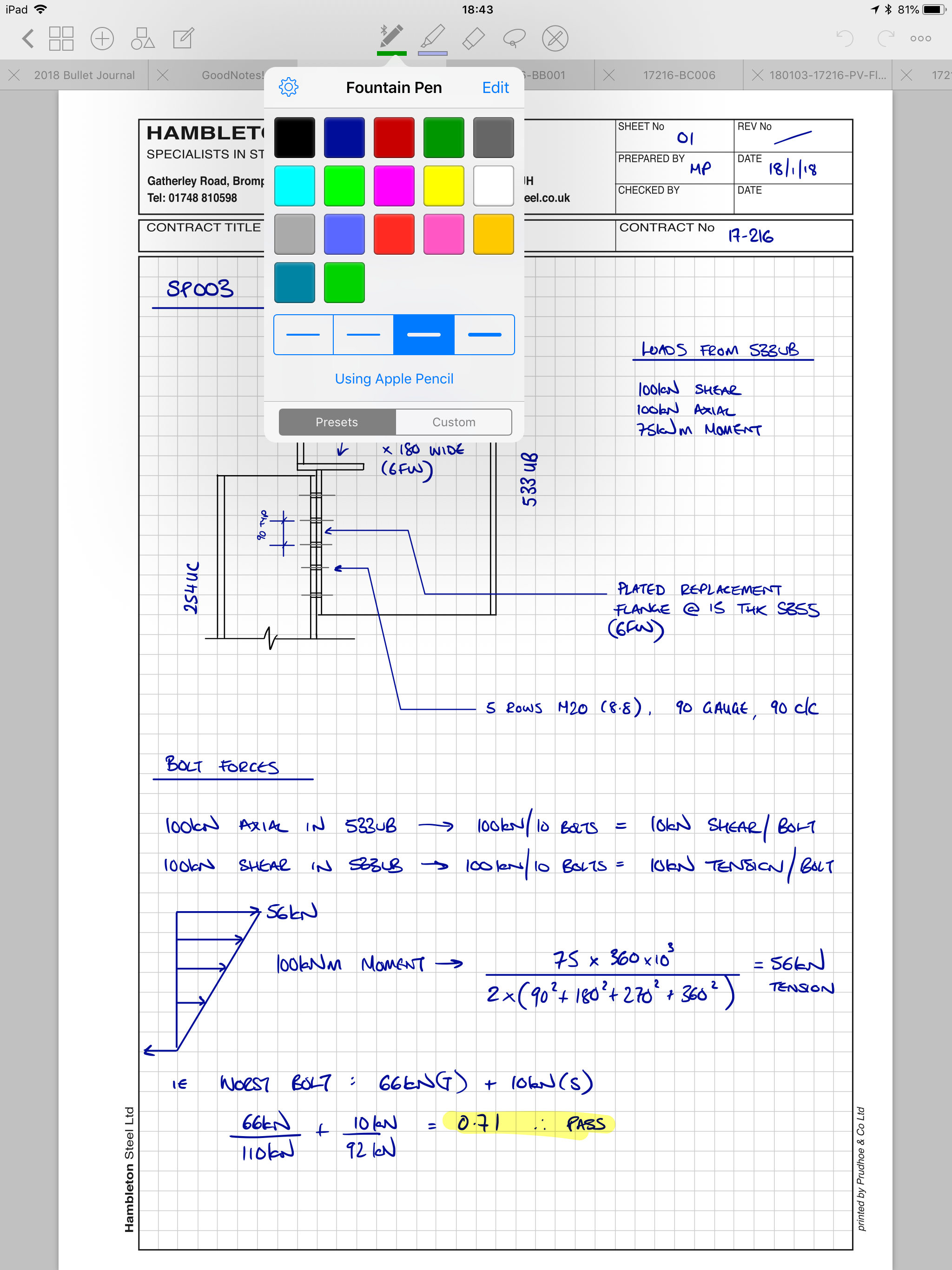
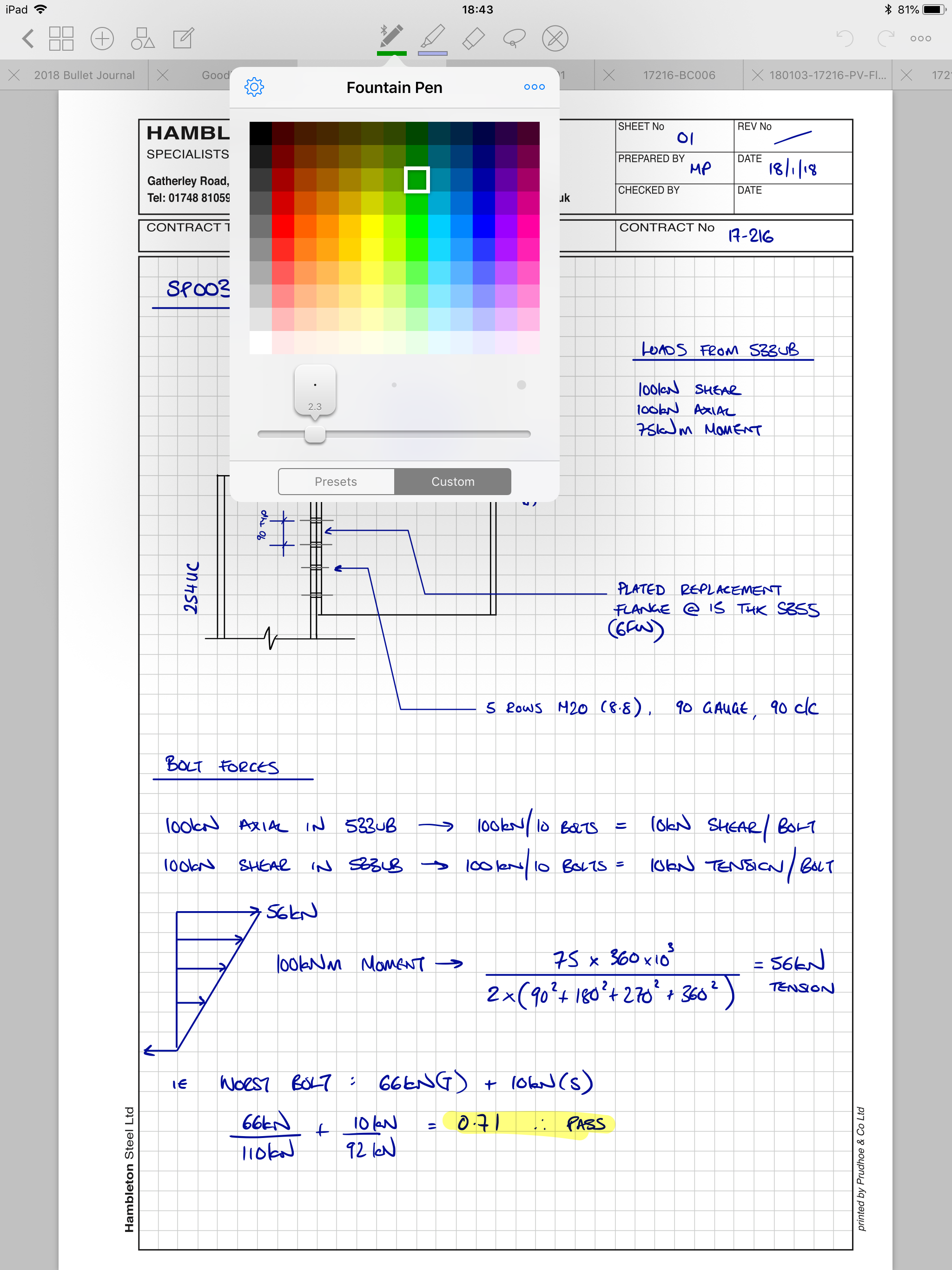
The pen tool can be switched from a fountain pen feel to a ball-point pen feel, and there are 15 preset colours to choose from. You have the option of expanding your default palette from a grid of 150-odd more, or the freedom to feed it hex codes for any colour you wish. There are 4 preset stroke widths to pick with, but they can also be adjusted with a custom slider. I’ve tweaked my stroke widths slightly and added two shades of green to my palette, but otherwise tend to stick to the defaults. My go-to colours in the fountain pen are the default deep blue, and a teal that I took from the expanded colour picker.

The highlighter tool has the same colour and stroke width customisability, and the transparency allows you to layer colours up too, should that take your fancy.

Aside from the excellent pen, there are tonnes of features that make GoodNotes ideal for engineers. You can:

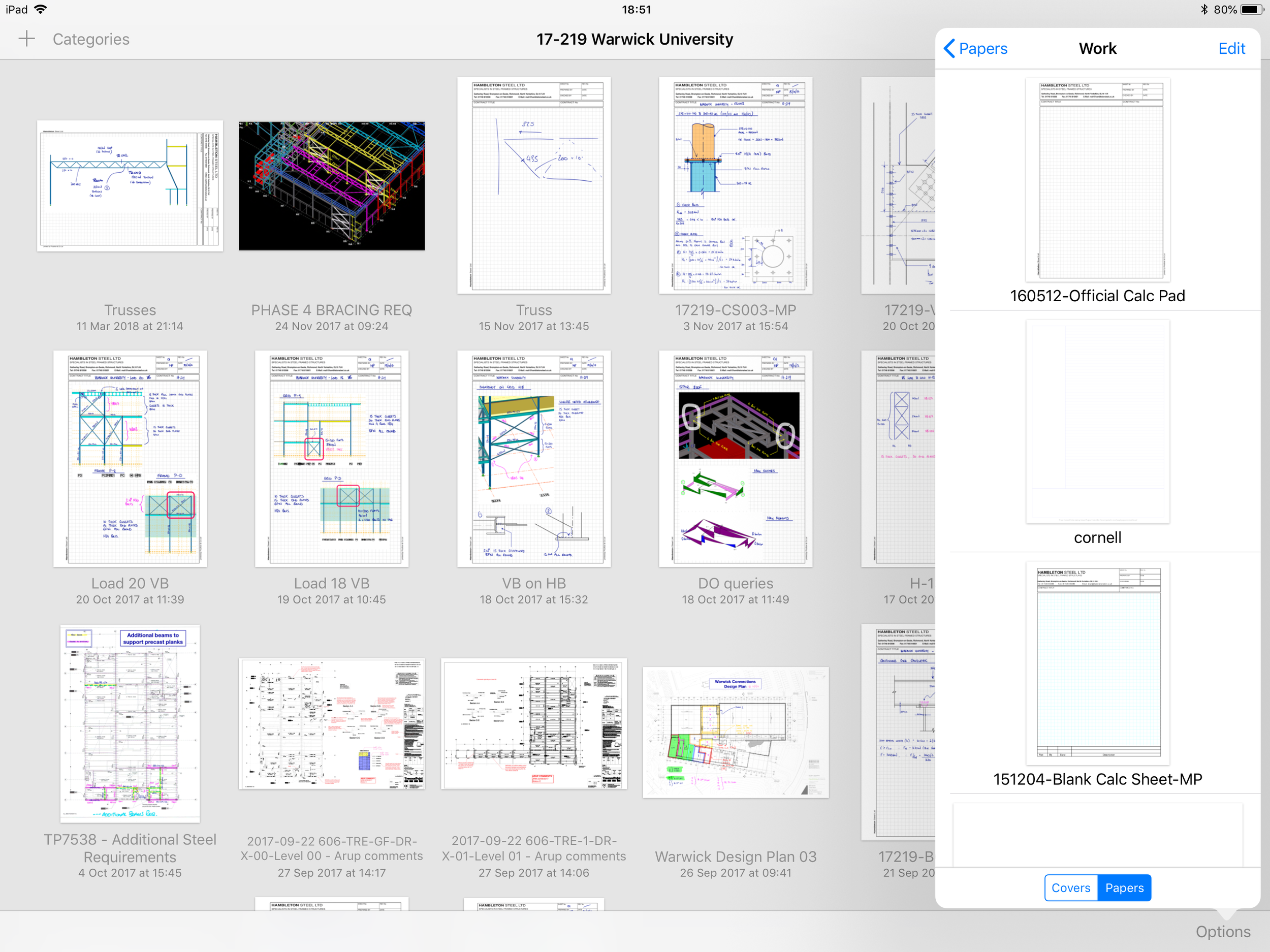
  • Import PDFs as templates into the app’s library. This is where I keep a copy of our company’s calc paper. New page creation is an absolute doddle when you are working too. To create a new blank page, you simply swipe past your final page and GoodNotes will insert a new page using the template you’re currently working on.
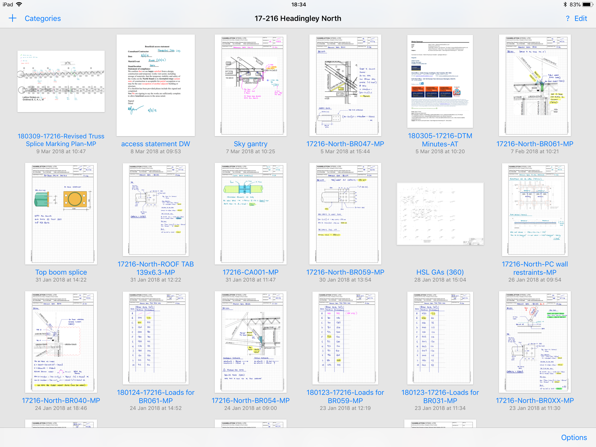
  • Import PDFs as standalone documents (from Dropbox or similar), or import them as new pages in an existing document. Want to import a set of architect’s drawings? No problem - you can decide either to import them as individual files (which you can view in separate tabs), or you can import them a single batch so each drawing is in one multi-page document with each drawing on a separate page.
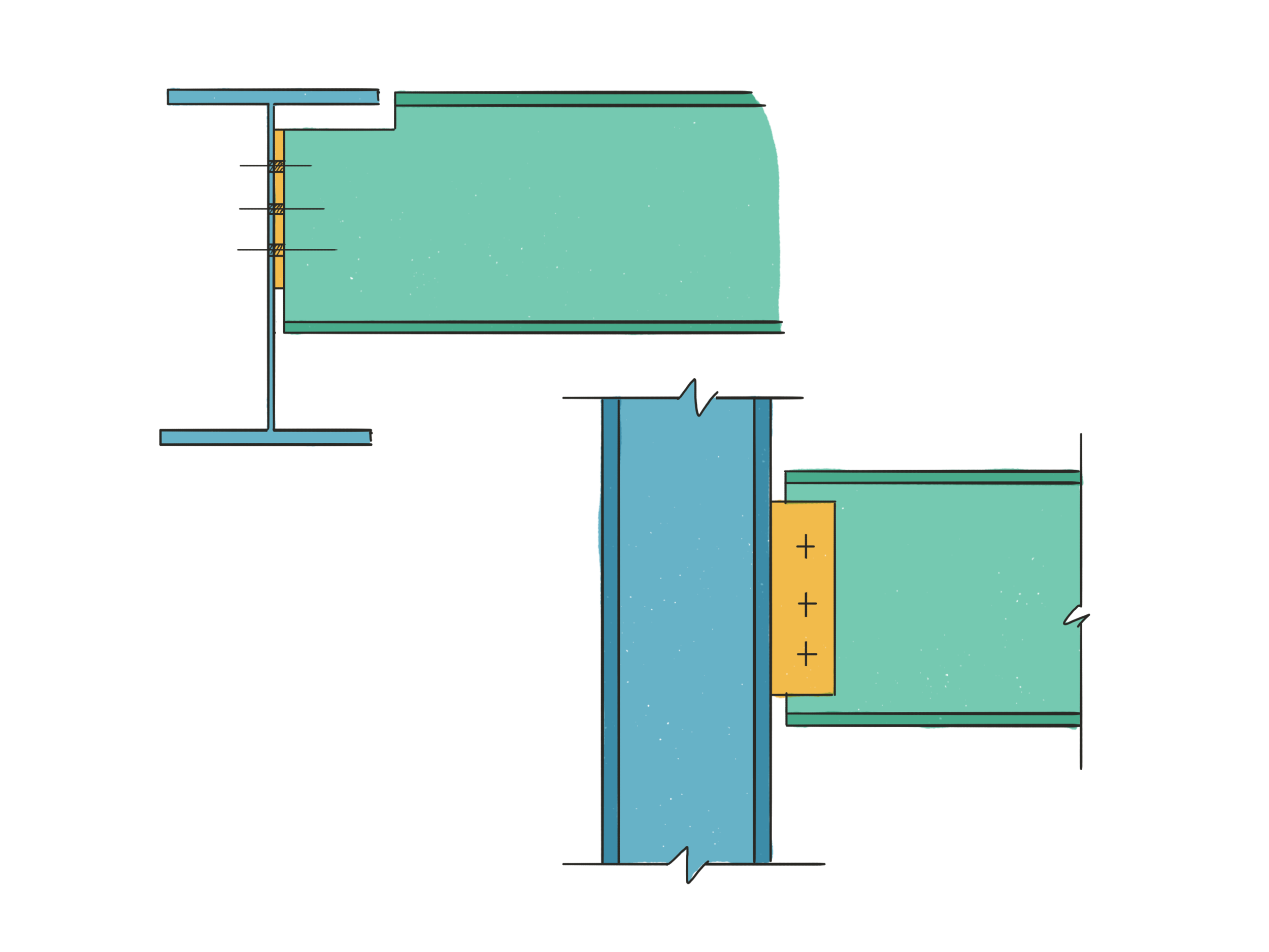
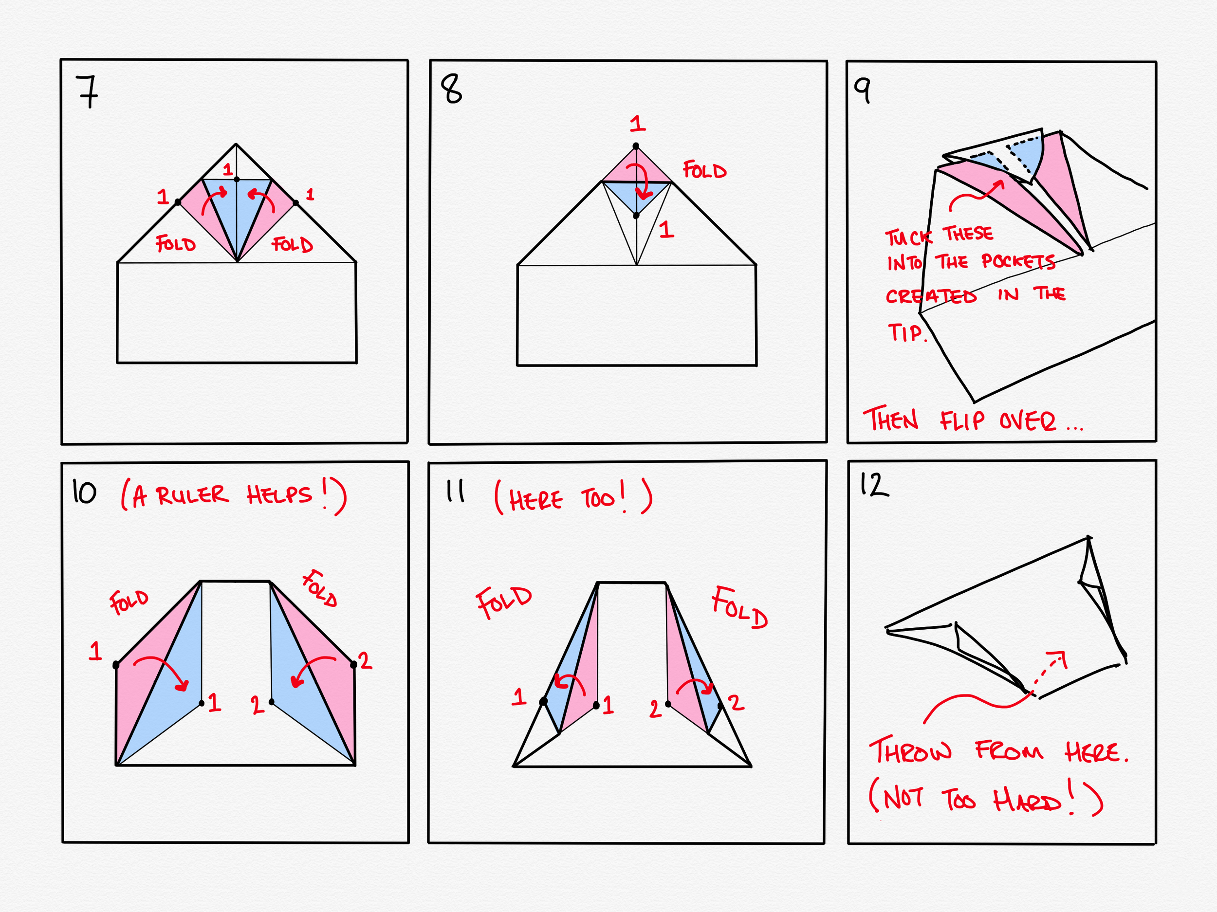
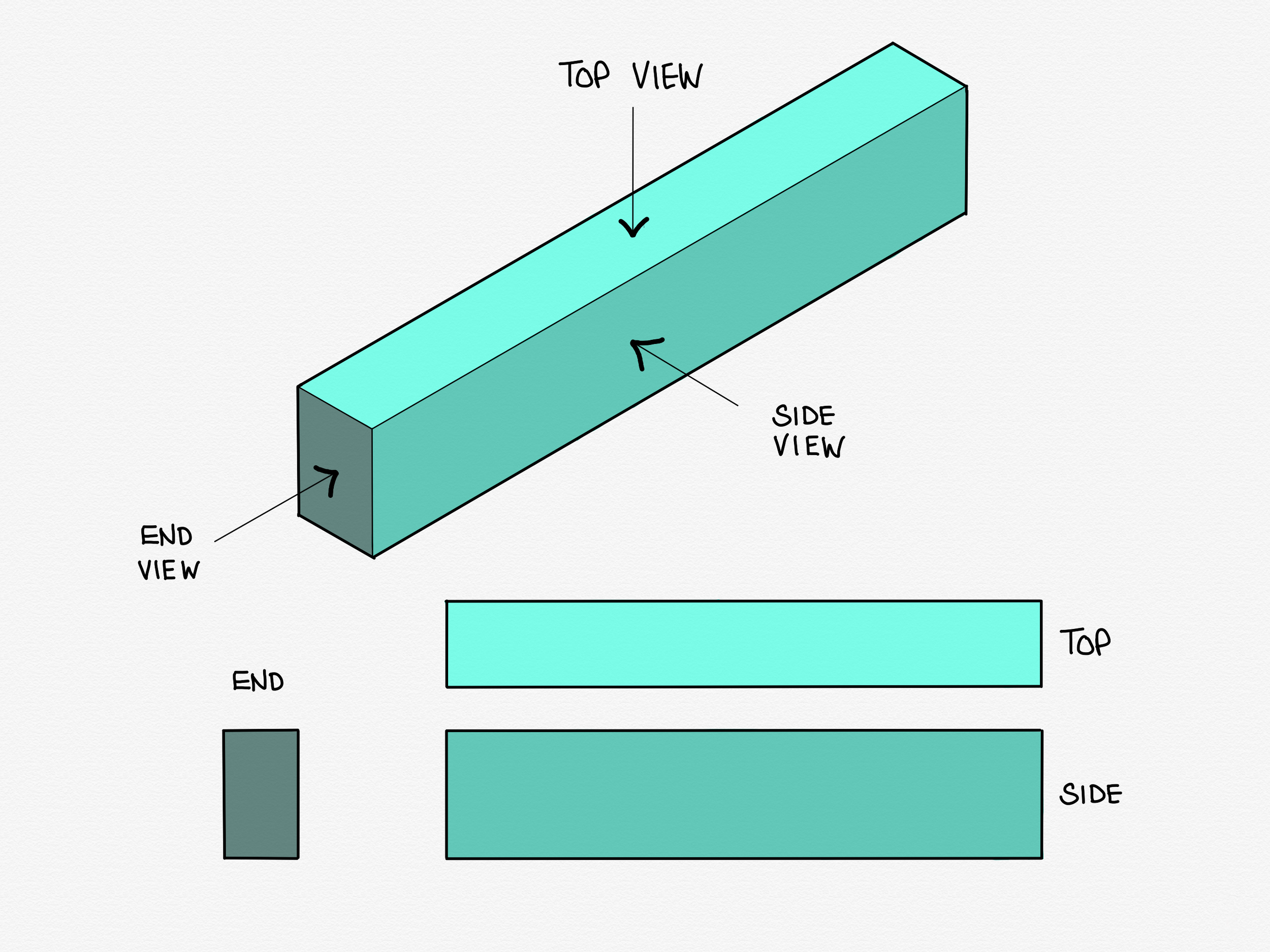
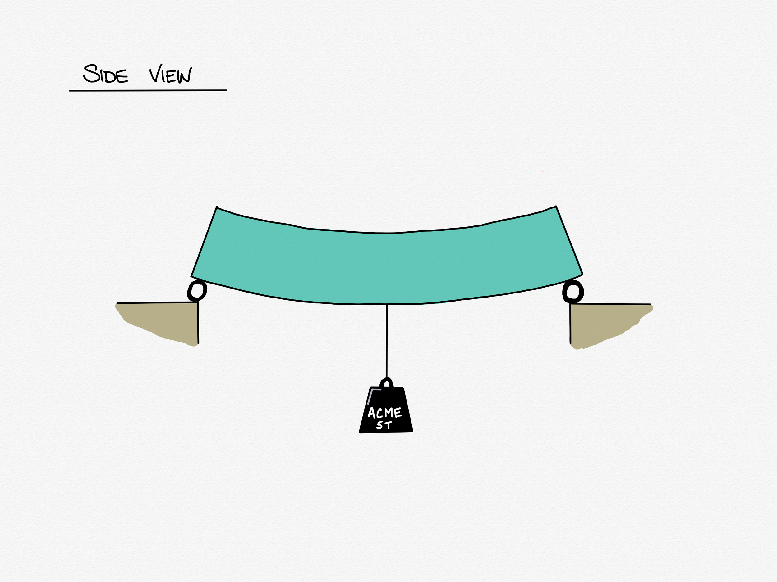
  • Draw straight lines and a few basic shapes with either the pen tool or the highlighter tool with a toggle. This is extremely useful for doing small sketches within your calcs, or neat dimension lines or leaders.
  • Use a lasso tool to select and move or copy any marks you’ve made. This is very helpful for sketches, and little things like copying titles across calc pages as well as just making everything line up nicely after you’ve done it. The lasso can be toggled to select any or all of handwriting marks, imported images, and text boxes. This is such a useful touch - if you’ve imported a snapshot of a drawing or design model and marked it up you can still tweak your marks without also moving the import underneath. 
  • Search within your notes for text including your handwritten notes. The OCR is pretty damn accurate.
  • Insert images and text, rearrange your pages and all the other myriad basics you’d expect. Especially handy is support for transparent PNG files, which allows seamless import of more complex sketches done in other apps. 
  • Switch the eraser tool from traditional to erase entire stroke. This is incredibly useful for correcting dense calcs. Also very handy if you want to draw some guidelines for writing, then erase them after.
  • iCloud sync means that everything on my iPad is also available on my phone. I personally don’t use the phone version for creating anything, but having access to absolutely everything I’ve ever written all of the time in my pocket has saved me on a good few occasions. 

Before I wrap up, it’s only fair I mention the few things that could be improved, particularly from the point of view of an engineer. I realise my wish list is both rather selfish and not necessarily aimed at the core market of the app, but I’d like to hope that improvements that fix the issues I have highlighted below will benefit all users... So, here goes:

  • Selected items cannot be scaled or rotated. This is a feature available in GoodNotes’ closest competitor, Notability, and I suspect is one the developers are actively working on. 
  • Whilst realising GoodNotes is a handwriting app first and foremost, the limitations placed on sketching are sometimes a drawback. For example, the straight line detection will snap lines drawn at shallow angles to be horizontal. A ruler tool like the one included in the Apple Notes app would be wonderful. Better yet if it could at least report the angle to the horizontal and better still if the user could define an angle to set it at.
  • If I’m being really cheeky, a straight up copy of Adobe Sketch’s French Curve tool would be lovely.
  • GoodNotes lacks a fill tool. A good deal of my time when sketching in GoodNotes is spent oh-so-carefully trying to use a highlighter with a circular tip filling in shapes with defined square edges without going over the lines OR taking the pencil off the screen. If you do either you have to start again if you want a neat block of uniform colour.
  • Bookmarks added to GoodNotes do not export back out to PDF. I believe this is also on the to-do list of the developers though.
  • Really getting nitpicky now: the default action when importing multiple items is to import them all as separate documents within GoodNotes. Getting them into a single document is a manual if fairly quick and simple process, but it would be lovely if the app were to ask if you want one document or multiple at point of import.

To summarise:

For the practicing engineer GoodNotes has almost everything you need to replace paper. Since getting my iPad Pro and GoodNotes about a 2 years ago I have not used a single sheet of calc paper. I still hop out of GoodNotes to create complex sketches in either Linea Sketch or Paper by 53 depending on the style I’m going for. Both of these apps are able to export transparent PNGs to import back into GoodNotes, blending them seamlessly into your calcs.

Given that GoodNotes is primarily a note-taking app, I can absolutely forgive it for not catering to my entire fantasy wishlist of features, and declare it truly and honestly to be the number one app on my iPad, head and shoulders above everything else.

GoodNotes, I salute you.

Connections: the basics

This is to be the first in a series of articles, where the aim is to introduce the different types of steelwork connections, when the various types should be used, and what ought to be considered in their application. I am by no means an expert in the field but I have 10 years of experience in designing connections, both for buildings I have designed myself and for buildings designed by others, so hopefully my advice is practical and useful if not necessarily academic.

I hope that this series will prompt engineers designing steel structures to consider how their selection of members constrains connection design, I hope it will aid connection designers from making avoidable elementary mistakes which, for example may cause members to be impossible to erect. I also harbour a deep hope that this series is at least informative and ideally at least a little bit interesting.

Steel to steel connections can broadly be split into two main categories: those which allow rotation, and those which do not. We call the former pinned connections and the latter moment connections.

Let’s start our brief overview on familiar territory; pins.

Pinned connections

At the end of our pair of prelude articles, we had defined what a pin connection is and how one behaves. Broadly speaking, pinned connections are typically used in the following circumstances:

Beam to beam, and beam to column connections

By far the two most common types of pinned connection are the first two - beam to beam, and beam to column, and as luck would have it, both work in almost precisely the same way.

bb-bc pins.png

Column to column connections (hereafter column splices)

Column splices are, even by the standards of a series of technical articles regarding steel connections, fairly dull. They come in two broad flavours, which I’ll cover at a surface level, and that’s about your lot.

col spl.png

Bracing connections

Bracing connections on the other hand are both varied and interesting. They take many forms and are often the most crucial connections in a structure. Correctly designing your bracing system is critical, thus ensuring the connections can transfer the loads as intended is equally critical.

bracing.png

Truss Connections

Truss connections are a fascinating topic to me as much because of the politics surrounding who actually designs them and at what stage in the design process as due to their inherent variability and complexity.

Truss.png

Moment connections

Moment connections, or moment resisting connections are effectively the opposite of pinned connections: they are designed to be rigid, i.e. they resist rotation. They come in all the same flavours as the pinned connections above, except for bracing connections. This is because braces should never bend, therefore their end connections should never need to be designed to resist bending.

Beam to column moment connections

These are probably the most common kind of moment connection by a hair. They come in a few main varieties, but by and large are fairly straightforward.

haunch.png

Beam to beam moment connections

These tend to follow the form of our column splices from the pinned category. As such, they aren’t massively varied, but nevertheless worth a short article on.

beam splice.png

Column splices

Much like their pinned counterparts. In fact so much so it’s likely I’ll cover both pinned and moment resisting in one article.

col spl.png

Truss connections

Moment resisting connections are rare in trusses - they only tend to appear in a specific type of truss called a Vierendeel truss, which is itself essentially a rigid ladder frame. The connections are straightforward beam to column type affairs, but the trusses themselves and the likely restrictions on connections are worth covering.

vierendeel.png

What next?

Having covered a lightning round of all the basics, I suppose it’s best to dive right in and begin at the beginning. Next time, we start on pinned beam to beam and beam to column connections.

As always, comments or corrections welcome at @martynpie on Twitter, or by email on martyn@martynpie.com.

All today's sketches drawn in Paper by 53.

Time, and fitting it all in

Today I want to talk about time, and more specifically the lack of it.

Previously, I posed the question “If it took a small team of consultants many months to design something in the first place, how then can one person replicate something similar in just a few weeks?”

There are a number of ways in which this is possible, some of which are more effective than others, some more interesting than others, and some more relevant than others given the applied time constraints.

In no particular order, and by no means not an exhaustive list:

  1. Experience    
  2. Shortcuts
  3. Excellent tools
  4. Cribbing
  5. Differing incentives

Experience

Coming in at number one, our old friend experience. It’s not interesting, but it is effective. Increased experience makes you better and quicker at every task you perform, and it makes you better at selecting the methods of getting a job done before your deadline. 

Shortcuts

Shortcuts, or rules of thumb, are used to take experience of past projects and apply them to the job at hand. The simplest example might be this: if you have previously constructed, say, a supermarket of area 500m² for a cost of £500k, you can assume that, roughly speaking, a similar supermarket of twice the size -  1000m² - would be twice the cost, or £1m. This is a powerful tool in your arsenal when time is tight, or details are scant.

Tools

The tools, or the *software*, at the disposal of an engineer working for a fabricator are the best there is. Whereas a consultant must spread their funds thinly to buy software covering all their competencies, a fabricator has just one section of the market to worry about. I’ve dealt with large multinational practices who have issues with sharing very small numbers of licenses between hundreds of staff for the very same software for which we have a copy for every engineer. For having the specialist tools for getting things done, we have an embarrassment of riches at our fingertips.

Cribbing

Cribbing is something we can and do take advantage of. Whilst we must rebuild from scratch everything the consultant has done in our software, whilst altering those details we feel will give us a price advantage, we do not have to replicate the toil of decision making and iteration that has led them to the design and thus the drawings presented to us. We must always take care to cast a critical eye over anything we crib, but it is an undeniable boon when we must work so quickly.

Incentives

Now, the differing incentives between consultants and fabricators is the interesting hook which allows our business of Design and Build to thrive at all. This section is different from the previous four: whilst experience, shortcuts, tools and cribbing allow us to save time, it is the way in which time competes with other factors in consultancy that provides Design and Build fabricators a niche to operate in. Allow me to explain:

When designing a structural frame, a consultant engineer is always mindful of the cost of his scheme to the end client - it must remain within budget or the project may not even go ahead - however this is only one of several competing factors a consultant must balance. For instance, the frame should contain some design contingency, that is to allow for some amount of unknown loading to avoid costly redesign should a client need to make small changes later in the design period. The frame should probably have a degree of rationalisation - that is keeping elements similar across the scheme to keep it simple at the cost of some extra weight. One other important competing factor is our theme for the day: time.

Consultants usually work on fixed fees on projects of a reasonable size - that is the cost of the design is agreed up front with their end client. The effect of this is that once a steel framed building’s design is stable, rationalised, checked, and within budget the only sensible thing to do is freeze the design, and get it drawn. There is no further benefit to the consultant for spending any time or resources to make the frame cheaper** to the client, as they won’t see any reward for any savings in the weight of steel made, in fact they will have wasted time: something of an act of self-harm seeing as consultancy fees are billed by the hour. The effect of this is that quite rightly, because of their particular incentives, consultant designs are often heavier than they need to be, which gives businesses such as the one I work for a unique selling point - we can take those designs, and use our skills as specialists to whittle out the excess in them and make the same building for less money.

** Note: the fashionable term in construction for “cheaper” is “more cost effective”. Whilst it avoids the negative connotations of “cheaper” I try to strive for clarity in language, so “cheaper” it is.

The Steelwork Fabricator

One of my key aims writing for this site is to try to explain what makes the role of a consultant engineer different to that of one at a fabricator. To get at this we must first look at how the two types of company operate. There is a single question which allows us to get quickly to the heart of the matter: how does each type of business make their money?

The key deliverable, the thing that you pay your money to a Consultant Engineer for, is information. You pay them for expertise, and they provide you with drawings, reports, specifications, letters, statements and expert advice. This information is then turned over to other professionals who may use it to construct a building or other type of structure.

The key deliverable of a steelwork fabricator is, unsurprisingly, fabricated steel. A client approaches you with the requirement of having the structural steel frame of a building erected where it is desired, when it is desired, and your job as a fabricator is to provide this, for a price.

But from an engineer’s point of view, here is where it gets interesting.

It is interesting because a client will approach you with a set of drawings already provided by a consultant engineer showing by and large, a completed design. A small team of consultants may have worked for months, sometimes years on a scheme design, represented in, for example, 30 or 40 drawings but it is presented to us as an opportunity to do what we do best: to take those drawings and try to come up with something better as an alternative.

And let’s be honest, what that really means, is to come up with something cheaper. 
Before we go down that particular rabbit hole, it is only right that I explain a little about the two broad routes a contract in this business can go down. The typical mix of the two types of contract vary over time depending on the economy, and the types of work in the market, but it’s near enough 50/50 for the purposes of this series.

Traditional Contract

Fabricators call these “Engineered” contracts.  In a traditional contract, the Consultant Engineer retains all design responsibility apart from connection design - more on that later. Those 30 or 40 drawings I mentioned above form the basis of the contract, and the fabricator is engaged to supply the steelwork shown on those drawings to the client; fabricated, connected and erected. 


Design and Build Contract


This is the type of contract I alluded to previously - fabricators usually refer to them as “D&B” contracts. Our engineers take on board the engineer’s drawings, their loading schedules, their specification and crucially a similar set of documents from the project architect, as well as other things such as end user specifications. They then have a handful of weeks in which to:


  1. Assess whether or not there are any changes that can be foreseeably made to a scheme to generate any savings significant enough to warrant doing the work in the first place.
  2. Assuming a route to cost savings has been established, effectively redesign the whole building, whilst not deviating radically from what the architect expects. Our new, cheaper structure will still have to fit into the zones pre-established by the architect.
  3. Price up the work, including the costs of (to name but a few items) running one or more factories, office overheads, materials, fabrication labour, profit.
  4. Prepare and submit a detailed quote, giving sufficient information to give confidence to the client that we have not missed out any vital details, but hopefully vague enough to stop our design being easily copied by a rival should the client want to pass our quote around to get a better price.
  5. Be prepared to chase the work, via phone calls, emails and meetings to do their best to satisfy any queries the client has, whilst making sure the quote is revised to reflect any changes brought to light since first submission.


You can see that an engineer working on winning Design and Build work at a fabricator is required to fill two major roles, and juggle a minor third one. The major roles are that of engineer and estimator. The minor is a sales role. We are typically juggling two or three of these roles at any given time, and to pull back the curtain slightly I also have a managerial role, and a somewhat accidental role as IT triage support. 


Working at a fabricator is an exercise in furious, existential plate spinning. It is however, very, very rewarding.


To finish - If you have been reading closely, you may have spotted me gloss over something that you might question thus: if it took a small team of consultants many months to design something in the first place, how then can one person replicate something similar in just a few weeks? Next topic: time, deadlines, and fitting it all in.

Bonus Content - Paper Aeroplanes!

When I was about 10 or so, my grandma once gave me a copy of a magazine; I'm fairly sure it was a Reader's Digest. Within those pages were the instructions to make a paper aeroplane - I vaguely recall it was some sort of competition winner or record holder. I committed the design to memory, and ever since it's been my go-to design for airborne paper hijinks.

I spent a futile 15 minutes this weekend trying to find some record of it online with the idea of first showing it to some family who were staying this weekend, then secondly of putting it up on Twitter. However, my Google-Fu let me down, so I decided I'd draw up a set of instructions of my own and post them here instead.

If anyone who sees this can find any proper attribution for the design, I'll happily update to include it, but for now, here we go...

Aeroplane - 01.png
Aeroplane - 02.png
  1. Fold down one of the top corners to its opposite side, make the crease sharp, then unfold.
  2. Repeat for the other corner.
  3. Fold horizontally back over, make a nice sharp crease, then unfold again.
  4. Bring the points all labelled 3 together, which should collapse all the pink area into the shape of the blue triangle.
  5. Fold up the loose flaps into the shape shown.
  6. Fold in the the corners again to create a kite shape.
  7. Step 7 I now realise (much too late to change it) is inexplicably a copy of step 6. You may safely ignore it and move onto step 8.
  8. Fold down the point as shown.
  9. This is the tricky bit. Unfold the pink parts - the top ones only - then tuck them into the pockets you find in the tip you folded over on step 8. You might need to bend them a little to get the in, but once you've got them slid in and flattened down then the whole thing will hold itself together solidly.
  10. Flip the paper over so you're now looking at the top of the plane - all the work you've done so far was on the underside - then make the folds as shown; these will be winglets. To get these folds exactly right it helps to use a ruler*.
  11. Fold the edges of the winglets back on themselves and then give them a gentle tug so they don't lie too flat to the body of the plane.
  12. Hold it by finger and thumb on the little pocket on the underside, and give a throw! It works best if you give it more of a deliberate straight push (a bit like a dart) than a throw.

Note: Don't bend it or fold it in half - the whole thing is a wing.

If you want, you can post photos your attempts to follow my hastily compiled instructions to twitter and mention me on @martynpie or you can be a crazy person and email me at martyn@martynpie.com

*I know, I know, rulers again. Sorry.

Prelude - part II

Today we pick up where we left off last week on our whistlestop tour of beam bending.

At the end of the last week we established that:

  1. If we apply a weight to a beam, it deflects downwards.
  2. The deflection causes the top half of the beam to compress, and causes tension in the bottom half.
  3. At the mid point of the beam there must be some amount of stress. 

Today, we are going to derive what happens all the way along the beam by paying particular attention to the very end points. We are in fact, going to begin by leaping right in with what happens at the ends of our particular beam.

If you recall the last post, I specifically said the end supports in our first example must allow the beam to rotate. There are both good practical and good mathematical reasons for this stipulation; the former we will cover another day, and the latter we are going to skip right over. For today we are going to start by accepting that the ends of the beam are allowed to rotate and that we call this a pinned support. Then we will consider what that in turn must mean for our bending stress at the ends of the beam. 

Pinned Supports

To explain why we have pinned supports and what they are I’m pretty excited to bring out the structural engineer’s most trusty, yet utterly unglamorous assistant to aid with the explanation: The ruler. Yes, the ruler. That 30cm shatterproof slice of secondary school nostalgia (but not those hinged ones that fold in half, sorry, but they were always rubbish) is every structural engineer’s best desk buddy. 

Behold, our beam as represented in compass-point graffitied, hi-res digital art!

IMG_0532.PNG

I know. Thrilling right? No really, the humble ruler truly is a useful bit of kit when trying to understand bending, I promise.

If you don’t have a ruler to hand to play along, I want you to imagine you are holding a ruler as drawn above, otherwise, go root around in your pencil case then come straight back.

Ready now? 

Great - let’s go. Balance the ruler on your fingers as shown in the drawing. Now keep your left hand motionless but raise and lower your right hand while concentrating on what you feel with your left fingertip where it supports the ruler. You feel the ruler rocking on your finger? It’s rotating freely. No matter how quickly or how forcefully you move your right hand you won’t change that fact - the ruler will always spin about the finger of your left hand. It sounds trite, but this is the perfect way to think of a pinned support.

Now why do we want pinned supports? The simple fact is that bending stress can never occur at a pin. Without something to actively resist the ruler, any bending you apply disappears at the pin. Try it yourself with your ruler! The simplest way to demonstrate it is as below:

Prelude Part 2 - 2018-05-03 20.51.44.png

You create a pin support like before with your index finger of one hand, let a decent length of ruler project past your finger, and force the beam to bend with your other hand. You can see that between the support (your finger) and applied rotation (your fist) the ruler bends, but at and after the pin the ruler is completely unbent - perfectly straight in fact, that is unless you’ve been abusing your ruler beforehand and if that is the case, frankly I can offer you no help there. 

The lesson to learn from this exercise is that bending, as we have defined it, cannot exist at a pinned support. Now, if bending cannot exist, the stresses - our tensions and compressions from the previous lesson - cannot exist either. If you stop and think about this we can say that we have now defined along our beam three points at which we have some idea of the bending stresses.

  1. We have the left support, where the bending stresses are zero.
  2. We have the middle of the beam (where the load was applied) where the stress is ... something.
  3. We have the right support, where the bending stresses are zero.

Let's put that on a drawing shall we?

Prelude Part 2 - 2018-04-23 11.56.28.png

Again, don't fret about the unfriendly diagram - just like last time it shows us what we already know. The pink shape I've sketched over the beam shows us what we have derived: there's no stress at either end, and some amount of stress in the middle.

I have made (and will gloss over) two assumptions .

  1. I have shown a linear distribution of bending stress - that is the stress varies in a straight line from 'something' at the middle to nothing at either end giving us a distinct triangular shape.
  2. I have assumed that the biggest stress occurs in the middle, where the load is.

I also know that I've left the actual amount of bending stress somewhat loosely defined in the middle there as 'some' stress, but frankly you've suffered enough if this is all new to you. Trust me when I say that there is a lot of unavoidable (but very pretty) maths to get to the true answer, which probably isn't even a topic for another day - it will take a lot to make that interesting enough to read for pleasure. 

But there it is - from nothing but a bit of common sense and a piece of plastic we've derived a way of showing bending stress distribution under a point load, and at the same time learned about pinned supports.

Next time I write on this topic, we can start getting into connections proper.

As always, comments and corrections are welcome either via email (martyn@martynpie.com) or via twitter (@martynpie).

Prelude part one - a rough guide to bending theory

Before I get into one the meatiest topics I want to discuss, connection design, I first need to explain the basics of beam bending. This is going to be an abridged lesson in two parts, and I aim to explain everything with only a scant reliance on maths. If I do this correctly, you shouldn't even notice the maths at all. Fair warning to engineers, I will very much butcher and simplify some concepts to make them approachable to all. 

Defining bending

I imagine most people are happy with understanding what it is to bend something. For instance, you might grab a ruler with a good grip at both ends and rotate your wrists resulting in a bent ruler. You might imagine a plank spanning between two rocks in a stream with a gleeful child bouncing right at the midpoint. The plank bends as the child lands and springs back to aid her next ascent.

That's a great start, but how do you truly define it? Let me explain.

I want you to imagine a chunky, longish oblong shape like in the illustration below, and imagine it is made of sponge. I'm going to refer to this from now on as our beam. It's important to always keep in mind that our beam is a 3 dimensional object, but almost all the drawings from now on will be of the side views or end views.

Prelude Part 1 - Isometric.png

Now we're going to bend our beam and have a look at what effects this has. To do this, we're going to support it at either end on something that allows those ends to rotate freely, and apply an imaginary weight to the mid-point.

Prelude Part 1 - 2018-04-19 11.08.46.png

Ok, so this is what we've got. Unsurprising right? The beam is bent by the weight hanging off its middle. This is what we call the deflected shape of the beam. In this case, the beam is bending downwards, which has the technical term (I kid you not) sagging. The opposite case, when a beam is caused to bend upwards, is called hogging. I promise you it's important to have words for both of these, but that's related to a lesson for another day.

To help us understand the effect that the bending is having on the beam, I'm first going to draw a line right through the mid point of our beam along its length, and a ghost image of its unbent former self behind.

Prelude Part 1 - Def Shape + Ghost + NA.png

Now it's time to take a look at our spongy beam and ask ourselves the ultimate scientific question: "what can we observe?"

If we take a close look, we can see that the bottom of the beam has actually stretched out a little, and the top of the beam has squashed in. This may not sound like a particularly thrilling observation, but it allows us to define a good deal of what's going on in any beam in bending, not just our spongy little friend here.

Given that our sponge beam is uniform in shape and material, we can make some simple deductions.

  1. If the top half of the beam is getting squashed, and the bottom half is being stretched, at some point the material of the beam must change from being squashed to being stretched.
  2. Our sponge beam is uniformly spongy, so a good guess would be that it swaps from squash to stretch halfway through the beam. 
  3. If you're on the ball, you may have already deduced that the line I drew through the middle of the beam represents the point where squash meets stretch. In fact, at the line, the beam is neither squashed nor stretched, it is perfectly unmoved. This line has a special name - The Neutral Axis.

This is good - we're making progress. Before I take us to the next step, we're going to move away from the words squash and stretch and use their engineering terms: Squash, we call compression; stretch, we call tension. Both of these we can collectively call stresses, and each of these two is the opposite of the other.

Ok, now onto some further deductions: For now, let's just think about the mid-point of the beam, that is, the point along its length from which we hung the weight.

  1. If the neutral axis represents a line through the beam where there is nether tension nor compression, we can say that there is zero stress along that line.
  2. If the top of the beam is in some amount of compression, and the bottom is in some amount of tension, but there is no stress at all halfway between, we can infer that the compressive and tensile stresses get higher the further away they are from the neutral axis.
  3. It then follows that the highest stresses are at the very top and the very bottom of the beam.

Let's smash open the beam and take a better look at what's going on inside:

Prelude Part 1 - Who needs a section.png

Now we're going to see what we call a 'section through' the beam, which is a quick way of saying "we are going to imagine you can literally slice/explode whatever we are interested in open and look at its insides". We're doing that so we can think about how the stresses vary from top to bottom.

Prelude Part 1 - 2018-04-20 19.08.12.png

Now don't freak out. I realise I've come in strong with a fairly busy diagram, but give me moment to explain before your eyes gloss over. All this shows is what we already know. The stress in the beam varies from the highest tension at the bottom, to zero at the neutral axis, to the highest compression at the top. 

In the most simplistic way, this is how we define bending - bending is directly related to the highest values of tension and compression stress caused by whatever is bending the beam at any given point.

Ok, so far we have established that there is some amount of stress at one point: the middle of the beam. For now, it doesn't even matter what that amount is. What we are going to be concerned with in the next article is how that bending stress varies along whole length of the beam, because what happens when we get to the very ends of the beam is the whole reason I've written everything so far.

Thanks for reading this far - I really appreciate it. If you have any comments or corrections, you can get in touch with me via email (martyn@martynpie.com) or @martynpie on Twitter.

Aims, topics, and breaking your own rules.

I currently intend to keep my articles here within at least a recongisable orbit of structural engineering, and my relationship with it. I also intend to limit the number of articles aimed specifically at engineers to something like every third piece. When I do write technical articles, I will still do my best to make them understandable to anyone willing to take the time to read them.

To that end I will endevaour to adhere to a set of rules I try to always keep in mind whenever I write at work, be that in emails, reports, or letters. These were set out by George Orwell in his essay Politics and the English Language in 1946:

1. Never use a metaphor, simile, or other figure of speech which you are used to seeing in print.

2. Never use a long word where a short one will do.

3. If it is possible to cut a word out, always cut it out.

4. Never use the passive where you can use the active.

5. Never use a foreign phrase, a scientific word, or a jargon word if you can think of an everyday English equivalent.

6. Break any of these rules sooner than say anything outright barbarous.

I must confess, many professionals in the construction industry are guilty of breaking all of these rules a good deal of the time. What is accepted as a "professional" writing style is often just poor writing: it is usually flabby, overwrought, and pompous. 

I also intend to abuse the sixth rule not only with regard to my writing style, but also my content. I will definitely write about topics outside the world of structural engineering.

I do have in a mind at least a few specific topics that I would like to write about at some point, including:

- Connections

- Paperless working

- Time

- My route to professional qualification

But for now, I implore anyone reading this to go and read Orwell's essay if you haven't already. It's not very long, freely available, and eye-opening. 


Welcome

I’ve been doing the same thing, more or less, for a decade now.

When someone is kind enough to ask me what I do for a living, the range of answers I give start around the vague, innacurate, but easily digestable “I sort of design buildings”.

I’d like to take you from that sketchy description forward, to paint a picture of what I really do,

I am a Structural Engineer, but not as you probably know them, if you already have an idea of what one is.

If a person has an idea of what a Structural Engineer is, the image they would likely have in their mind would reflect a Consultant Structural Engineer; someone who works across projects in many fields. They might come to your house to advise you about a domestic extension, or do high level design of an office building, or design bridges. They would work across multiple materials; reinforced concrete, timber, steelwork, masonry or even more esoteric materials like structural glass.

Quite by accdent, I sidestepped this life in favour of specialisation.

Shortly after completing my degree I found myself working almost exclusively in structural steelwork, starting with a two-year stint at a now defunct structural steelwork fabricator in West Yorkshire specialising in Design and Build. This is where my journey into specialisation began. In the run-up to its collapse (see: Global Financial Crisis of 2007-8), I was offered a job at a small consulting practice in my home city, which I gladly took. Almost a year to the day later, a former colleage approached me to join him at another fabricator, this time in North Yorkshire, and there I have remained for the last 8 years.

The life of an engineer working for a fabricator is very different to that of a consultant, and as I write this welcome piece, I believe that difference is one of the main topics I want to explore here. It is exciting that public awareness of engineering as a whole is increasing, so I hope that I can contribute to a modest bump in the awareness of my small, and perhaps overlooked field.

The first question I must now ask myself is “does anyone care?” followed swiftly by “is this even interesting?”. The answers I give myself are “well yes, I do” and “I truly hope so” respectively. I don’t know who will be keeping score for me, but whoever they may be, I hope they are kind enough to let me down gently if I’m wrong.