Yearly Theme - Getting Things Done

Let’s kill two birds with one stone!

Bird one: a topic I promised myself I’d write about.

Bird two: life update slash list of excuses for not writing very much.

Stone: this year’s theme - Getting Things Done

For the past few years I’ve been a fan of the Yearly Theme, as opposed to New Year Resolutions for reasons covered in depth on the Cortex podcast. The quick version goes like this:

Resolutions are often pass/fail, for example:

  • I will start running

  • I will go to the gym regularly

  • I will get a promotion

The minute you skip a run, or don’t wake up in time to go to the gym, you’ve failed, so you can stop trying. And people do, in droves. It’s been a meme for years in fact.

Themes are wider, and more flexible. They can be bent to your will. For me last year was the Year of Lean. I could make it mean whatever I needed, but the essential features of the Year of Lean were to lose some weight, and to reduce the amount of “stuff” in my life. It worked magnificently.

  • Chucking out old jumpers I didn’t need: Year of Lean!

  • Unsubscribing from email lists I never read: Year of Lean!

  • Managed to get out for a run every so often: Year of Lean!

  • Chose not to eat a massive burger and had a salad instead: Year of Lean!

  • Breaking free from listening to multiple tech podcasts which previously fed my rabid gadget fetish: Year of Lean! (Sorry ATP guys)

This year has been at once more successful, and less successful. We are now beginning the eleventh month of the Year of Getting Things Done, and hoooo boy, the Big Thing that had to get Done has very much Been Done. It has been hard work doing so, and it has come at the expense of essentially devouring the year in one gargantuan mouthful.

That Big Thing was of course moving house.

I am very satisfied to report that Family Pie have successfully moved about 300 metres up the road to what is essentially The Dream House (also known as “the house they’ll take me out of in a box”). As you may have read, we had some bumps along the way, but that’s all in the past. We’re in, we’re happy, and we have since doubled our cat quota.

The house has a kitchen big enough for the three of us to eat in, but also a formal dining room for when we have guests. It has a decent study as far away from the front door as reasonably possible, a playroom where all Mini-Pie’s bulkier toys can live, and a guest room on the top floor. We are extremely lucky, and we know it.

But.

The other big goal of the Year of Getting Things Done was to make a sizeable dent in my path to professional qualification (Chartership) and that has essentially come to naught. Now that we’re settled in and all urgent repair and upgrade works are done on the house, I will have more time to dedicate to it, but I am a little disappointed in myself that so little was able to be done this year. Ah well, such is life.

Rather than dive straight back into the Chartership drive, what is left of this year will be dedicated to getting the house ready for Christmas. Funnily enough, I don’t usually get too excited about decorating for Christmas, but I think with a new canvas I’m a little bit over-eager to paint. That, and come up with next year’s theme. I haven’t given it a moment’s thought until ... well actually just now.

Best get on that really.

The B Word and the D Word

There is an unwritten rule for this blog which was, within reason, to stick to evergreen topics as much as possible to keep articles from becoming dated. Relevant to the topic I’m about to write about however is a conflicting rule: I want to write about things that I am passionate about. This essay has been burning in my belly for some time now, but current events have brought it up to the figurative boil.

For historical context, I write on the 1st of September 2019. The current UK government has declared that Parliament shall be prorogued from the 9th of September 2019 to the 14th of October to, in their words, deliver a Queen’s Speech laying out their future business. In reality, the biggest impact of this prorogation (the longest in decades) will be to limit the available time for Parliament to legislate against the Government’s current policy of trying to ‘run down the clock’ and allow the UK to leave the European Union without a Withdrawal Agreement. This weekend has seen mass protests across the UK with citizens in outrage of the proposed prorogation, viewing it as an affront to our democracy. Just this morning Minister without Portfolio, Michael Gove has publicly admitted that should the UK Parliament manage to pass legislation to prevent the UK leaving without a Withdrawal Agreement, the Government may choose to simply ignore it.

In simpler words, the Government might choose to ignore UK law if it serves its interests. This is a Very Bad Thing.

For many reasons it is very difficult to express a balanced view of the current state of UK politics, and how it is viewed by the wider public. For instance:

1. The animosity between either side of the Brexit debate is fierce. To express an opinion counter to the extremes of either group is to brand yourself a ‘traitor’. The language being used to describe people across the political spectrum is venomous, dehumanising, and massively unhelpful.

2. Because of this resentful divide, it becomes difficult for people to decouple actions or words that benefit their partisan aims from actions that are shortsighted, divisive, or unlawful.

3. As a result of this difficulty, there is a wide and particularly problematic misunderstanding of the already vague word ‘democracy’.

So before we talk about why the current UK Government is doing demonstrably terrible things with obvious and avoidable negative consequences for the UK as a whole, we need to talk about The D Word.

Democracy

What even is democracy?

Depends who you ask doesn’t it? In the UK we operate a Parliamentary Democracy. Under this system, to massively oversimplify, our country is divided into small areas called constituencies, and each constituency elects a representative (Member of Parliament, or MP for short) who then divides their time between their local area, and time in London at the UK Parliament.

First point of confusion. Many people disagree about whether or not their MP is simply meant to ‘tell Parliament what the majority of people in the constituency think’ or whether they are meant to act in the best interests of the constituents even if their best interests run counter to locally held opinions on the matter.

The wording in the YouGov poll isn’t precisely the way I would have put it, but you can see the broad strokes.

The wording in the YouGov poll isn’t precisely the way I would have put it, but you can see the broad strokes.

In my opinion, this should not be up for debate. The reason we elect representatives, is because we can task them with taking the time to understand and therefore vote in good conscience on issues we neither have the time nor the capacity (on average) to do so. I like to think myself a relatively intelligent person, but do I want to spend dozens of hours poring over fishing policies, proposals on changes to inheritance laws, or defence budgets? No, frankly I don’t. I have taken the time to vote for a representative who will do so on my behalf. Neither do MPs operate in a vacuum: when I have opinions on upcoming policy I can make an appointment to visit my MP to inform them, or write a letter, or send an email.

But the fact remains, that a significant portion of the public are of the belief that their MP should just ‘do as they’re told’ (aside: do you think people who hold that opinion would want to be an MP?). So even before we move onto ad-hoc referenda which are in conflict with our already ‘established’ version of democracy, we already have a difference of opinion over what our country’s version of it is.

Referenda

Our next flavour of democracy is the Referendum. I am sure all readers are aware we had one of those not so long ago, and ever since then its effects are inescapable. Let’s face it, as you read this very text you are metaphorically entwined in its betentacled clutches.

You right now.

You right now.

In the UK, a referendum is a nationwide vote on a particular issue which is meant to be binding on the government of the day. It is very understandable version of democracy, a question is asked or a policy is put forward to be either rejected or accepted, and winner takes all.

This simplicity, I would argue, is part of what makes some of the current language, propaganda, and slogans being used so attractive to people, in particular those who voted to Leave the EU. A very simple argument to form is “we won the referendum, do as your told and leave the EU”. It will be relevant to note that the referendum chose by a narrow, and now famous margin of 52% to 48% to leave the European Union. It was not a resounding victory by any means.

There are fundamental questions to be asked regarding the way the 2016 EU referendum was crafted, because with a little more care and forethought, the very real economic, and now Constitutional uncertainty caused by it could have been avoided. The open-ended question of *exactly how* the UK was to leave the EU, should the populace choose to do, so is the very reason there is now such confusion about democracy.

Democracy vs. Democracy

I am emphatically not a lawyer, so I am utterly unqualified to debate the merits of which of these two forms of democracy should trump the other, but it is obvious for all to see that there is an ongoing conflict between two competing democracies, and for the purposes of this essay, and being able to correctly judge the UK Government’s recent actions, that there is an unresolved conflict is all that matters.

It is easy to find comments on websites, placards at rallies, and quotes on vox pops on the news saying that to protest against the prorogation of Parliament is “anti-democratic”, because it subverts the “will of the people”. This is plainly only part of the story, because as we know there are two democracies in play. One of the democracies chose the direction of travel - that is the Referendum chose to leave - and the other democracy, our Parliamentary democracy, has been left to figure out exactly how it is should be done. Both are legitimate, and neither can or should be ignored.

The most obvious way to get around this fundamental impasse would be some sort of compromise: the UK would leave the EU in a way which the 48% of the public who wished to remain can be in some way placated. Unfortunately for fans of practical solutions that might just about please everyone a little bit, three successive UK Governments have by negligence and choice made compromise essentially impossible.

The slow death of compromise

The Cameron government devised the 2016 referendum badly, and then failed in the campaign to call out lies by the Leave campaign in at attempt to avoid damaging inter-party public arguments. This allowed the Vote Leave campaign in particular the latitude to frame the arguments in the most base and false ways, and marked the start of a ratcheting of rhetoric across the whole of the debate. Compromise was already under threat from the uncontrolled lies spread by Leave UK and the combative and negative tone they set.

The May government was the first to actively choose to throw compromise in the figurative bin. After an initial period marked by silence and evasion, May decided to trigger a snap election, actively seeking a mandate to enact her Brexit strategy. The election resulted in May losing her majority, with a return to a hung Parliament. The country effectively said, “we don’t particularly want what you’re offering, and we feel much the same about the opposition”. At this point, May ought to have recognised the country’s need for compromise, but instead veered maniacally into a brick wall as she began to behave as if she’d won a thumping majority. The UK was to leave on what was, in terms of all referendum campaigning and political speculation since 2016, the very hardest of Brexits. The ratchet moved another tooth on its travel.

Now we arrive at the Johnson government, and in the space of a few short weeks we’ve moved from May’s policy of Very Hard Brexit, to Johnson’s policy of seeking to leave without a Withdrawal Agreement at all. It is important to note that under the May government, MPs from all parties voted for and passed legislation demonstrating a firm rejection of taking this action, deeming it economic suicide. A similar group of MPs are planning to do so again.

I feel I need to remind everyone, that this where public opinion was in 2016.

I feel I need to remind everyone, that this where public opinion was in 2016.

So, compromise is dead, and Winner-takes-all politics becoming the new norm under PM Johnson, probably due in part to the success of President Trump. Political norms can no longer be taken for granted, as a politician operating with wrecking tactics simply ask themselves “what are the costs of breaking these rules?”.

Bollocks to the rules

Prime Minister Johnson’s chief advisor, Dominic Cummings has been held in contempt of Parliament, yet is now one of the most powerful people in Whitehall. What tangible, life-affecting cost has been borne of his being held in contempt? None. He probably has an official letter telling him as such, which he has either framed, or shredded.

Johnson and his team under Dominic Cummings will be looking at every gentleman’s convention that can be waived, every prerogative power that can be abused, and now any laws which can be simply ignored and asking themselves: “what can be gained by doing this, and what will it cost us?”. As with Cummings’ contempt, many of the costs will be “none at all” and many will be “none in the short term”.

Except not.

Because this returns us to our first question: what is democracy? We might not be able to get anywhere near a consensus on what democracy is, but we can agree what it is not.

It is not sending the voting body away for 5 weeks because they might force you to do something you don’t want to.

It is not ignoring laws which do not suit you.

It is not (as is currently reported as a possibility) sacking and deselecting any MPs which vote against the government.

(Note: this is one of the reasons I want to get this out now, before it’s outdated. By tomorrow lunchtime there might be a bloody general election on the cards and all this becomes somewhat redundant)

All these moves have a cost, and that cost is the erosion of our Parliamentary Democracy. Whichever way you voted in the referendum, allowing a government to act in this way allows all future governments to do the same, and any one of those next times they will probably do something you disagree with.

And yet you may cry: doesn’t allowing MPs to block No Deal defy the other democracy; the referendum result? Well no, it doesn’t at all. All the referendum result does is declare that we should leave, not how. The method of leaving has been left to the Parliamentary democracy, and Parliament must be allowed to operate.

Anything less is not democracy.

Mobile office

Some people, especially people on the internet, love to know what gear you use, so as an easily digestible piece of written content: here’s what I carry when I am out of the office.

Because I’m writing this at the weekend, I’ll start with my weekend bag, which I like to think of as my writer’s bag:

I use a Visconti messenger bag and the usual contents are pictured below:

Weekend / writing

Everything about my weekend bag is getting down to the minimum viable amount of things to get any amount of writing or sketching done should I get a free block of time. My primary writing device is my venerable iPad Pro combined with an absolute star of a travel keyboard. The K380 is perfect for my needs: it syncs with my iPad with no fuss, and it works happily with my MacBook Pro regardless of whether it’s booted into OSX or Windows 10. The included set of AA batteries lasted about 10 months, and it’s survived one decent coffee spill and a pretty significant drop onto a hard floor so it definitely counts as rugged. As backup, I’ve got one straight up Moleskein notebook and one pen, and for keeping my fingers busy when I’m thinking (procastinating) I carry my Qiyi Warrior 3x3, which is a cheap-as-chips intermediate speed cube.

Aside: I am by no means a speed-cuber: my average solves take about 90 seconds, but the stickerless Warrior 3 is about half the price of a Rubik branded cube, and much faster, quieter, and lighter.

Ever present in my bag is my Frank Green travel cup, which I adore. I think they’re pretty damn stylish, they’re fully recyclable, you can configure your own colours, and replacement parts are available at prices not designed to gouge your eyes out. Oh, and you can open and close the drinking hole with one hand, which is extremely helpful.

If I’m travelling and will need my laptop, I carry a Thule Stravan rucksack, which not only accommodates an abundance of gear, it comes with dedicated storage for my MacBook Pro 15”. My bag is a very fetching shade of purple which I can’t find any more, but the cobalt blue in the link is a good enough match. It also has a dedicated iPad sleeve at the back which fits iPads up the old 9.7”. size. I love it, and I’m even minded to buy a pre-emptive replacement for mine at the price in that amazon link, because I paid about twice that when I bought mine back in 2015.

The contents on a typical day are below:

rucksack contents

New items over and above the weekend bag are:

The extras (other than the laptop) are mostly based around going to meetings, hence the abundance of extra pens for marking up drawings, the business card holder and the battery pack. If I’m going to meetings my phone tends to take a hammering, either just via train travel or quite often because of tethering. I can usually get through a day travelling with my (now two and half year old) iPhone 7, but it’s touch and go by evening so I tend to use the charger if I get any downtime to top up.

I carry the USB mouse, because if I need my laptop, I’m almost certainly going to be using 3D modelling software or plain old 2D CAD. Good as the trackpad is on that 15” Pro, it cannot hold a candle to a mouse with a scroll wheel that doubles as a third mouse button for panning in either of those cases. I could have splashed out on a wireless one, but they’re heavy, and I’d need to carry spare batteries.

The knife is just one of things you never know when you’re going to need, but I’ve lost count of the amount of times it’s come in useful. I’ve had it since I was about 18 I think; I can’t really remember a time as a functioning adult I haven’t had my Swiss Army Knife. The monocular is handy on sites for being able to look at construction details from outside of exclusion zones, or at height when you don’t have access. It’s not exactly essential, but it’s come to find a place in my travel bag, because the times I do need it tend to be when I’m out and about rather than at home or at the office.

Note: none of these Amazon links are affiliate links. I wouldn’t even know where to start setting up that kind of thing.

The year of the move

It’s been a busy time at Pie Towers recently. Pies Mr, Mrs and Mini have been trying to move house for some months now, which at the best of times is tricky but as it turns out our timing was… well let’s say that the timing has been deeply unhelpful.

It’s time for a barely edited ramble:

My wife and I had earmarked 2019 as the year we would leave our beloved mid-terrace just outside of York city centre and try to find something a little bigger with more separation of living spaces. We knew we couldn’t bear to leave our central location as we are utterly spoilt for schools, for the community, for the much beloved high street round the corner, and for almost car free living outside of my work. Essentially, we were looking for exactly what we already had, exactly where we already were, but… a bit bigger. So far, so simple, but also so constrained.

As luck would have it, exactly what we were looking for was in fact right on our doorstep. We found a beautiful end-terrace we could afford with loads of corridors and twists and turns just up the road. It was perfect: all we had to do was get our house sold.

And therein laid the rub.

Overshadowing our whole adventure was our country’s dalliance with unprecedented international self harm. The ‘B’ word. The Bad Thing.

We had sold our house subject to contract after just a few weeks of viewings. At the time it was interesting to watch how certain events in Brexit Calendar affected the mood of house buyers. The week leading up to the much delayed ‘meaningful’ vote depressed viewings to effectively zero. Once the drama had passed, viewings were up to a half dozen every ten days or so. If I spoke to people about The B word, respondents fell broadly into two categories: the first were just depressed about the whole thing, and subsequently couldn’t imagine buying or selling a house under such circumstances; and the other group were of the opinion that it would all come to nothing, and no tangible effect would ever be felt.

Then the Big One hit home. Three weeks before our intended move date in early April, our buyer pulled out, citing Brexit uncertainty as one of their main reasons for deciding not to buy.

What followed was two months of frantically trying to find a new buyer in time to keep our upward chain intact, despite the omnipresent B word. Mrs Pie and I would typically spend a good hour to ninety minutes preparing our house for a viewing and looking back through my calendar I can see we did this no less than thirty times over the whole period from January to today. I dread to think how much time I’ve spent on the phone to our estate agent, and that of our vendors in this time, as well as time spent conducting viewings our agent couldn’t attend (Sundays, Bank holidays, and times that just didn’t work) and writing emails to everyone involved.

Fast forward to this weekend, and for now, the worst is over. After all the effort we do have a new buyer in place, and despite the fact that nothing is stopping this new buyer from pulling out, I’m going to let myself enjoy this period of what feels like both emphatic victory in the face of insurmountable odds and also relative calm after a frankly atrocious couple of months. Our whole upward chain remained intact, in part because our vendors withheld from going back on the market for weeks to allow us as much time as they could, despite the house they were intending to buy was put back up for sale within a week of our buyer walking.

We are very grateful. Even if things do fall apart again, I’ll take the hit from allowing myself to just believe that things will go well this time. That’s my choice as an optimist. I think that’s easier than the alternative.

So tonight I look forward to a week at work where I am no longer in two mental places rather than one for the first time in what feels like six months, but in reality has only been about eight or ten weeks. And maybe in the evenings I can start to think about the fun parts of moving: getting rid of old junk, figuring out how we’re going to actually live in the space, and I can definitely see this as a great hide-and-seek house. Someone mentioned a housewarming party the other day; if this all goes through, I can tell you that there will be a hell of a party once we’re moved in.

Fingers crossed for us?

Thanks

1.2 - Communication

Objective: Ability to demonstrate effective communication and interpersonal skills

I’ve never imagined that I might struggle on this requirement, in fact, I’d be surprised if many candidates slip on this. The guidance starts by saying that candidates should “demonstrate competence in effective communication and interpersonal skills using written, oral and visual media. I like to think I’m fairly proficient in writing, speaking and sketching which covers the main bases there.

The guidance goes on to list a plethora of ways a candidate should demonstrate their ability to communicate via:

1. IT links

2. Produce spreadsheets

3. Produce database documents

4. Develop an ability in writing letters, summaries and reports, both factual and interpretative.

5. Where appropriate develop drawing skills

6. Be able to produce drawings to illustrate concept appraisals, feasibility studies and initial design details.

7. Have the ability to prepare and deliver presentations, project précis or design concepts etc.

8. Have an appreciation of the skills of other professionals in the construction team and demonstrate an ability to work as an effective member of a team.

Looking at items 1, 2, and 3 I feel like the advice might be a little out of date. I don’t know many engineers who have to produce “database documents” and I’ve never even head of “IT links”. As it happens our estimating software is built off a database, but frankly I don’t think being able to use it has the least thing to do with communication. 

Similarly, letters have been mostly replaced with email which is one of the cornerstones of communication in modern engineering. I imagine if I were to take a look at the sheer amount of email I’ve written in the past decade I’d have some sort of Total Perspective Vortex moment and be struck down with inescapable horror at the amount of time I spend hammering at my keyboard in an attempt to keep the business moving. I must have written at least one or two decent ones that can go in the portfolio. I’ve had to write some factual and interpretative reports in the last few years as well, so I can certainly tick off that particular box.

I try to draw for pleasure in my spare time, and I hope it shows in my work. My sketches are mostly of connections, and sometimes of general construction details, but hopefully their colour and clarity of line work makes them stand out. I like them. Owing to the nature of the work of a fabricator I don’t have masses of sketches of concept appraisals, or feasibility studies; we’re usually a long way past those stages by the time we get hold of a project. I must say I do wonder where it would not be appropriate to develop drawing skills though…

With regards to delivering presentations - it has admittedly been a while since I physically stood up and delivered a formal presentation, but I’ve never shied away from standing up in a room and making myself heard, and by Grabthar’s Hammer I do so enjoy making a good slide deck. 

Of the last item on the list, I feel I’m particularly well placed. I have spent the vast majority of my career at a level where I am present and active in regular design team meetings giving me a good all round appreciation of the input of the other professionals. On top of that my Masters degree was cross discipline for the first two years, then specialised for the final two. The “selling point” of that particular degree was really to produce multi-disciplinary consultants, and whilst for me that emphatically did not happen (hence, well, this entire blog), it does give me a decent appreciation of the other engineering disciplines and how they fit in with construction. 

In summary, without sounding smug - I think this section is not going to present a worry to me.

Bonus video content

Things have not gone well with our house move (thanks, Brexit), so here’s a time lapse video of me assembling the Lego Creator James Bond Aston Martin DB5.

Stick around till the end for the added bonus of seeing my contemptuous cat eyeballing the ejector seat in slow motion with his typical disregard for all human activity.

I had to film it over two nights owing to an evil stomach flu. You’ll notice a slice of my birthday cake going uneaten across the first half of the video. I also blame that for the mistake I make with the ejector seat mechanism…

An Open Letter

The below is a copy of a letter I sent to the IStructE this evening in response to a letter published in the Verulam pages in the February Issue. I reproduce it here lest it not make the cut - I expect there will be quite a few letters in response to this one.


It’s difficult to know exactly what to write in response to the letter by Cliff Billington in the February 2019 issue of The Structural Engineer, owing to my conflicting desires. I would on the one hand like my words on the matter to be printed, but not to the exclusion of any writers who have things to say on the matter, crucially those who are not men.

I should like to examine a few key passages of Mr Billington’s which I have issues with:

“A recent Viewpoint article stated that ‘One of the biggest problems in our profession is a lack of gender balance’. Since when?”

Not being an expert on the detailed history of our profession, the most specific answer I can give to this question is “since the very beginning”. The idea that any profession could possibly be somehow improved by doing nothing to reduce the exclusion of half the population is utter madness.

Then we arrive at a passage which I expect will inflame many, many people:

“Maybe young women simply do not want to be engineers - standing in mud and being cold, and wet, on site, in foul weather - and would rather embark on a different career?”

Maybe we should begin by not presuming to know the inner workings of the minds of an entire group of people? Maybe that presumption is incredibly offensive, and is fuelled by hurtful, inaccurate, lazy stereotypes of the worst kind?

Maybe we should consider the systemic barriers in all our workplaces that inhibit the career progression of women? Maybe we should start by examining our long-held prejudices, which have been left unchecked to spread like a disease over generations and are now finally being exposed across many fields, from science and academia, to the media.

With few exceptions, the smartest people I have worked with as a colleague, or worked with as part of a design team, or studied with in my university days are women. We must do everything we can to promote gender equality for the sake of all, and not be distracted by spurious arguments about failings in the “whizz-kid[s] with finite element analysis or advanced computer packages”. Such problems may be real, but they are a fixable thin end of a relatively new wedge, as opposed to a glaring, fundamental error the entire construction industry has been making en masse for decades.

I would have liked my first letter to Verulam to have been more positive, but I could not let such outdated views go unchallenged.

Martyn Pysanczyn

1.1 Institution

Ok, so we’re off to a slow start. Attempting to move house has taken up a good deal of my usual writing time; weekends and evenings have been eaten by either viewing potential houses, or frantically scrubbing our house in preparation for someone else to come here and view it. I’ve stolen 45 minutes today to abscond to my favourite local pretentious cafe to try to get my thoughts in order.

Objective: Knowledge of the Institution and involvement in Institution affairs.

Where I am told that Knowledge actually constitutes Knowledge and Understanding of the subject and its application. Taking the guidance from the Mentors Handbook, the candidate should:

1. Demonstrate a knowledge of the structure and purpose of the Institution of Structural Engineers, together with an awareness of the Institution’s Code of Conduct.

2. Attend technical meetings and seminars (recommended 3 per year OR equivalent involvement in other professional Institution or relevant CPD activities)

3. List the involvement with a brief overview of all the activities and a brief commentary on two events

4. Have an appreciation of the institutions of other disciplines

Let’s see how I stack up.

Knowledge of the structure and purpose of the IStructE is an easy one. I went on a course provided by the Yorkshire Branch of the IStructE with the explicit objective of filling gaps in candidates’ knowledge that are required in the 13 Core Objectives that they may not naturally acquire in their careers.

There, I learned that the IStructE has a Dual Role (we were encouraged to shoehorn that in) as both a Learned Society and as a Qualifying Body. In plainer language the IStructE encourages and enables learning, professional development and research for the benefit of all and publishes original guidance of its own, whilst also acting as the entity which confers qualifications on Structural Engineers via its Professional Review and Examinations. It is the gatekeeper.

Anyone who reads The Structural Engineer will also be abundantly aware of the Code of Conduct, as the results of hearings are published within. In a nutshell, the Code of Conduct is the official list of rules we are bound by as professional engineers. I admit I have not read them front to back, but I suspect if I go by the watchwords of Apollo Flight Director Gene Kranz I’ll be ok. This is what he said the morning after the terrible Apollo 1 fire - these are words I think about a lot:

From this day forward, Flight Control will be known by two words: "Tough and Competent." Tough means we are forever accountable for what we do or what we fail to do. We will never again compromise our responsibilities. Every time we walk into Mission Control we will know what we stand for.

Competent means we will never take anything for granted. We will never be found short in our knowledge and in our skills. Mission Control will be perfect.

When you leave this meeting today you will go to your office and the first thing you will do there is to write "Tough and Competent" on your blackboards. It will never be erased. Each day when you enter the room these words will remind you of the price paid by Grissom, White, and Chaffee. These words are the price of admission to the ranks of Mission Control.

Gene Kranz, 30 January 1967

Ok, moving on - we now have to contend with the attendance of technical meetings and seminars (or similar approved...) at the approximate rate of 3 per year. I remember the last one I went to, it was about the restoration of Walmgate Bar in York, but I cannot even recall one before that. I need to get out there and do more. This is going to require sacrificing a little family time because more often than not the Yorkshire IStructE seminars are in Leeds and Sheffield. Leeds isn’t so tricky, but Sheffield’s a right old trek on a school night. Wondering aloud, maybe I could do webinars?

*frantic researching*

Oh this is good. Lectures at the London HQ are recorded and uploaded to the IStructE website. I can watch a bunch of these and makes notes for my portfolio. Hopefully there’ll be some that I can make some good sketches for too; I feel like doing some artwork after all this typing.

Lastly comes appreciation of the Institutions of other disciplines. I mean I’ve heard of most of them, and I assume they are broadly similar to the IStructE (but if what I’ve been told in the past is true most if not all have much lower barriers to entry). I did have a meeting with someone from the ICE whilst in my first job about becoming a member, but was immediately put off by his manner. I used the word “Institute” and the guy reacted by haughtily informing me that “women have Institutes, We have an Institution. In disgust, I threw all the admission forms in the bin straight after. Probably best not to mention that on the form.

Ok, I reckon I’ve got the bones of a final IPD form here. I’ll get to drafting that while writing another ramble about section 1.2, Communication.

IPD forms, according to the IStructE

Given that my personal writing style leans toward the ... er... informal, I’m turning to the advice of the very people who will judge my forms to get some general advice on how to put together the IPD forms via the IStructE Mentor Handbook. Some of the advice is stylistic, but much of it is advice on appropriate content. I suppose I’ll have make an effort to no longer lean on imaginary conversations with myself as a framing device and also my proclivity for parenthetical asides for the time being. Ah well.

There are three sections on general advice for IPD forms in the Mentor Handbook - let’s go through them.

Make it personal

This one is perfectly straightforward. The examiners are not in the least interested in what my company has done, they are interested in what I myself have done. I don’t think I’ll have a tendency to waffle about the achievements of my company, but I’ll have to be careful not to let myself colour the prose too much with ‘fabricator this’ and ‘fabricator that’. That’s what this site is for, not my IPD forms.

Make it positive

The advice given here is split into two threads in the Mentor’s handbook. The first is to not concentrate on weakness, but strength. Again, I don’t think I’ll be struggling with this and to me at least it seems obvious: I’m meant to be selling myself.

The second thread is more about precision with language, and as the designated Office Writing Pedant I think I’m actually particularly well suited to keeping my prose relevant and accurate. The examples given are twofold. First, remember to use the language of the requirements: if a section is written to demonstrate ability I must use words like able and ability when describing my ... abilities. Secondly, it advises against qualifiers and weasel words, like ‘somewhat experienced’ or ‘limited knowledge’. This is one of those things that sets me off anyway: to give you a window into my personality, I had to really strain not to send a specification back to a 3rd party for using the term ‘fairly unique’ with red pen in the margins.

(Not that I’m in any way perfect - I expect that I make every grammatical mistake that I decry at least once a day)

State how you have achieved the required standards

This is explicit instruction to get to the point and not waffle. Candidates have in the past been caught out by describing the standard they must achieve rather than laying out the reasons that show that they actually meet the required standard. I do like to prattle and chat, so I will have to make a concerted effort to keep myself on track and to explicitly blow my own trumpet rather than talk around the problem.

Enough writing about writing

This is my first day on my schedule for getting these forms done, and I write to you from a short respite in getting my house ready for a viewing. This post is somewhere around 25% procrastination, 25% preparation, 25% getting myself into the habit of writing quickly, and 25% getting into the habit of writing when I can squeeze it in. Gotta form those good habits folks; it’s going to be a rough 20 weeks.

Let’s smash this. Next job, first draft for form 1.1 - Institution (Required standard K - Knowledge).

The Second Major Theme: Getting Chartered

Right back in my early days of writing here I wrote a post called “Aims, topics, and breaking your own rules”. One of the topics I said I would cover was my route to professional qualification. I reckon it’s time we took a break from responsibilities in connection design and introduced another theme.

Context: The year of Getting Things Done

I use Yearly Themes rather than New Year’s Resolutions. Last year I had a successful Year of Lean where I made a real effort to:

  • Streamline my commitments (I gave up being a School Governor amongst other things).

  • Streamline my waistline (I took up running).

  • Streamline the amount of stuff I need, keep or use.

This year’s theme will use the time and discipline I’ve gained from last year and allow me to Get Things Done, and one of those Things I want to Get Done is to make a significant step forward in my route to becoming a Chartered Engineer.

You mean you aren’t Chartered yet? What have you been doing with yourself? You’ve told me you’ve been doing this for ten years you lazy monkey!

I don’t want to lay this out as “Martyn’s excuses for not doing his homework” however I do feel strongly that the deck is stacked against engineers working exclusively in fabrication who started their careers around the financial crash of 2007. To paraphrase an old friend from school “I prefer the team reasons or explanation of events to excuses”. Let’s explain those … events.

Lack of Mentorship

When I was a graduate at a fabricator in 2006/7, things were actually peachy. There were multiple Chartered Engineers of regard within our organisation and we had a solid graduate training plan. The business itself was created by engineers, and run by engineers. Come the crash however, the first thing to go was training. No longer could Wednesday afternoons be spent in the meeting room doing CPD, as every man was straining to keep the business afloat. As it happened, I left that business some months before it failed, and subsequently after a year of working for a small consultancy found myself back with my old team leader - let’s call him Chris, because ... that’s his name - at another fabricator (where I’ve been for 8 years now).

This time around, we were it. Chris and I were the entire design department. The business we entered had previously done no more than 1 Design & Build project per year up to this point, and we were to take that up to 5 or 6 per year between the pair of us with immediate effect. It would be unfair to suggest that we somehow resented this new independence, in fact we both thrived on it, but the lack of available mentors was tough. Who would sign off our quarterly reports? Nobody that we knew, and would we even have time to do them given that we had a voracious fab shop to feed? As it turns out, this was a good time for rapid on-the-job learning that would serve us both well, gaining bags of practical commercial experience and cranking out calculations to keep the fab shop fed, but it was not a great time for Chartership progress.

To cut a long story short, moving into a business that isn’t run by engineers or have established senior engineers in place isn’t a great place to be for professional mentoring. Don’t get me wrong - it was superb for many other reasons, and given the same choices again, I’d still be exactly where I am now. Over those 8 years, I suppose I have become one of those experienced engineers we didn’t have when I started, and I hope that my legacy in the company will be of finding new talent to replace myself, and putting in the systems to allow that to keep on happening. Time will tell.

Specialism

There is a good deal to be said for specialism, especially from my personal experience. It’s brought me to where I am and I am grateful. It has not exactly been an especially useful route to Chartership though, it must be said. I have spent an entire career minus one year working in businesses where the only material I am required to design is steel. The year I did spend in consultancy I hoped would gave me an opportunity to spread my wings a little. It would however turn out that the forces of business decreed that my previous experience in fabrication meant that I was given all the steelwork gigs that came in that year, and opportunities to master the other common construction materials were limited. If I’d stuck it out, maybe things would have evened out over time. I will never know.

Could I have recognised a lack of professional progress in fabrication and changed jobs to further my development? In theory I could have, but in practice not so much. I had already taken a large pay cut to move into consulting for that one year (owing mostly to my specialism), but then came the family. I primarily moved back to fabrication for the money, as I now had a tiny mouth to feed and would likely need to move house. I could make the years I’d spent previously in fabrication count for me rather than against. The timing was fortuitous - I hadn’t planned to move out of consulting, but it was Chris that came knocking just as my wife was 9 months pregnant with our son. Back to specialism I went.

So fast forward 8 years and now I have reached an age and position where another move back to a consultancy would bring such a large pay cut as to be effectively financial ruinous. I have to forge a path forward from the chair in which I sit, and I have to be the one to make it work.

So what’s the plan?

I have one route to Chartership open to me: the retrospectively collated route. I have to:

  1. Complete 13 Core Objective Final Reports.

  2. Compile two hard copy portfolios of my work, referenced to those Core Objectives.

  3. Find 2 existing Chartered Members who will sign my application form, having seen my work and agreeing that I have reached the required standard for Professional Review.

  4. Find a Fellow of the IstructE to do the same. Note: my first attempt at contacting a previous lecturer resulted in flat refusal to even consider such a thing. This step truly worries me, owing to my relative insulation from the wider profession.

  5. Attend and pass an interview which is designed to find the gaps in my knowledge of which my specialism creates many. In phase two of the Year of Getting Things Done I must do something about these gaps.

  6. Pass the final written exam. Strangely, this step is the one which many of my peers felt would be the toughest. Perhaps unwisely, I believe that if I can get to the test, I’ll be very much ready for it.

Yikes. Probably best to break this down into more manageable chunks.

Agreed. Right now I think there are two broad areas I should be focusing on:

  1. Getting the 13 final reports written, and my portfolio put together. This will satisfy my first two goals and identity any areas that require consolidation.

  2. Making some connections in the wider engineering community, via this website, social media, and attending more IStructE events to give me a fighting chance of not being stumped by requiring signatures from Chartered Members and a Fellow who don’t know me well.

I’m hoping that making connections can mostly look after itself without dedicating too much specific time to. That leaves the IPD forms and the portfolio.

If I want to be ready to submit by the beginning of September, that leaves seven-ish months. In round terms, that’s 28 weeks to complete 13 forms and create a portfolio. One a fortnight would be cutting it too fine, so that means I need to try to plan which reports I will have no more than a week to get done, and which I can or should take more time over. I’d like to have the reports written by week 20, giving me something like 2 months to finalise the portfolio and garner some signatures.

I think the best way to stay accountable here is to draw up the plan, and post my draft reports here as I do them.

It is time for the excuses to end, and time to Get Things Done.

Pleasant Interlude Number 2: Linea Sketch 2.5

Turns out I’m a fickle beast.

I spend 1000 or so words singing the praises of Procreate after their update last year, and here I am now re-enraptured by Linea Sketch by iconfactory.

The main reason I went looking for other sketching apps after spending lots of time with Linea Sketch 2.0 was the lack of a fill tool. The primary reason I’m now back on the Linea bandwagon is the introduction of … a fill tool! But there’s way more to this update for engineering sketching than just a simple fill tool, so let’s take a look at the shiny new features.

ZipShapes

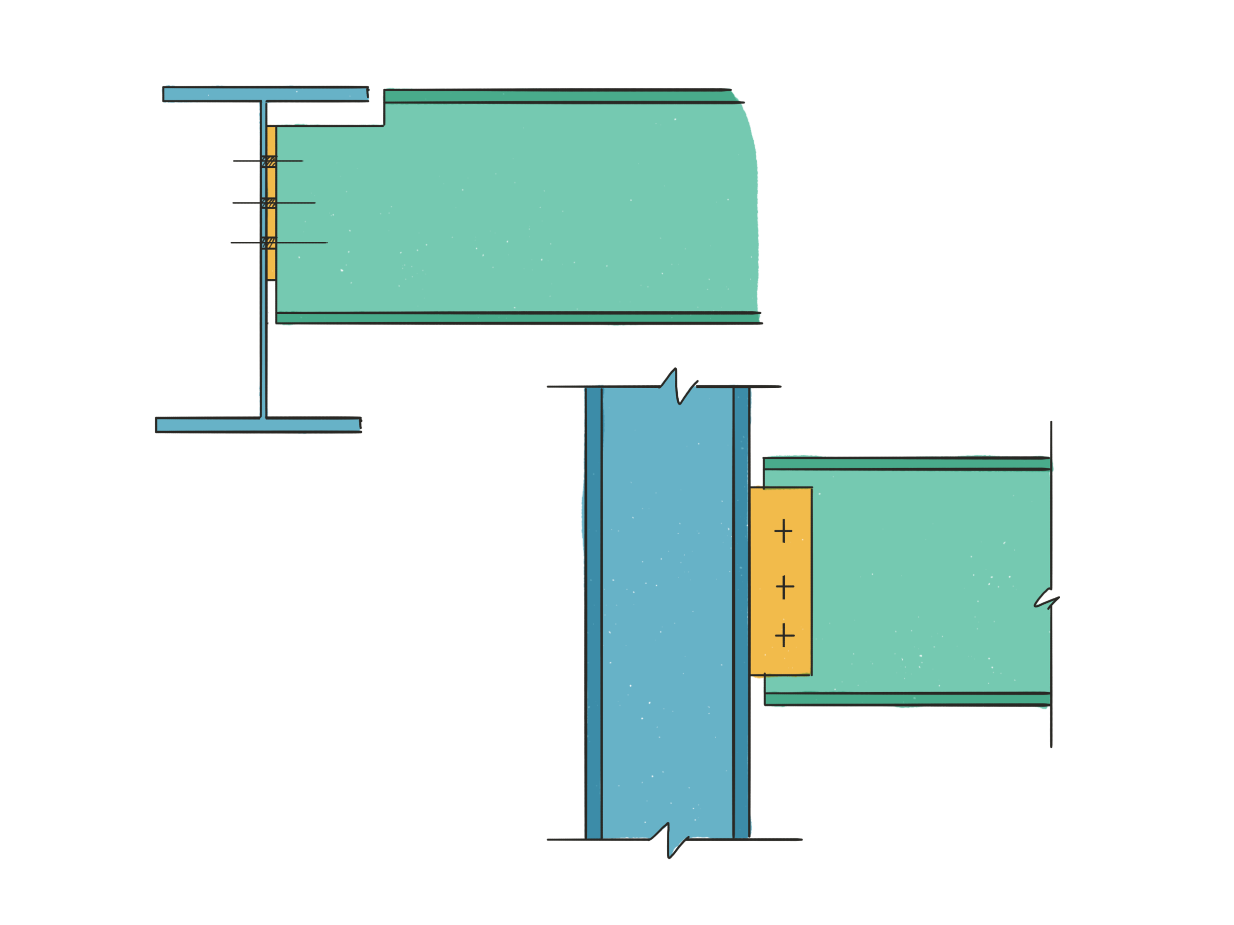
As an engineer drawing a large amount of steel detail sketches, I often find myself drawing a good deal of things that look like variation of this:

And now I have a tool that helps me do this much more quickly than before: ZipShapes. Rather than me blather on, let’s attempt some video content...

Before version 2.5 this would have taken me a couple of minutes to do to my satisfaction. The version in the video took 18 seconds.

As well as squares and rectangles, Linea 2.5 recognises circles, ellipses, triangles, and finally irregular polygons; the latter being what it falls back on when it cannot reconcile your doodling to a regular polygon.

Combined with a select tool which can filter by layer you’ve got a very simple to use but very powerful method of creating a good looking line drawing.

Fill Tool

This fill tool though, oh this fill tool. What I love about iconfactory is the way they put in so much thought into their very few tools. It’s like going to a new cafe or restaurant and noticing with pleasure that the menu is small. You know that care has been taken to ensure that although your options are somewhat limited, whatever you do have will be excellent.

The fill tool has two modes: tap to fill, and freehand. The freehand method is, as far as I can tell, broadly same as that in Paper by 53 (another great sketching app, but more free-hand and watercolour based). You select a colour, whether or not you desire transparency, then you draw a shape. The resulting shape is converted to a block of colour with no outline.

Tap to fill is where the real action is at though. The way icon factory have configured it is just genius. It works like the old paint bucket tool in MS Paint, but cleverly with your layers and even guidelines. The fill tool essentially reacts to whatever is on the screen, and ignores whatever is turned off. The fill is made on the currently selected layer, regardless of which layer the detected boundaries are on.

I love this thing.

My usual workflow is to do everything first in blue pencil on my bottom layer with the small 4x4 guidelines switched on, then when I’m happy I ink over that on the topmost layer. When the inks are finished, I use the middle three layers for colours, centrelines and labels. All I need to do to throw in my colours is turn off my pencil layer, centrelines and the guidelines to show just my final ink outlines, select my colours and tap away. Super fast, super obvious, and incredibly helpful.

Ever since seeing Glen Cooper’s (@AvatarEngineers on twitter) vibrant hand calcs done on an iPad 4 or 5 years ago, I’ve endeavoured to get some colour into my sketches because it just brings them out beautifully. The issue has always been time - colour used to take time away from the calcs, and was only something I could afford to do when it was really necessary; now it’s such a quick job it’s crazy not to colour my sketches.

Blending and Versioning

I’m just throwing in a mention for these two new features for completeness, as I’ve not had any real interaction with them. Blending is something I almost certainly will not be using in my day job, but I expect the support for reverting drawings to a previous state will be very useful in the future.

In Conclusion

Linea Sketch 2.5 is all sorts of my jam. If you are an engineer doing hand calcs on your iPad, you ought to be using this. It’s just the best.

Responsibilities part three - joint resistance in hollow section trusses

Welcome to the most trivial hill upon which I will gladly die. Also, when I say trivial really I’m trying to manipulate you a little with self-deprecation. It’s not trivial; this issue is a constant pain in my proverbial butt-weld. This is in fact, to me, The Big One.

Much like an item mentioned previously, the web-to-flange welds in plate girders, it’s hard to see how the responsibility of this particular design element ever moved from consultant to fabricator. In fact, both situations are directly analogous. I hope to persuade all who read this missive to join me on my hill, trivial or otherwise.

Ok - so what’s got your knickers in a twist? 

I’m going to lay this out one step a time as if I’m Hercule Poirot himself explaining to the reader exactly how events must have unfolded so as to arrive at the unavoidable conclusion that he is (or in this case I am) correct. Let’s begin at precisely the wrong end: the assumed and false denouement, the thing that has, in fact, got my knickers in a twist.

The claim: the steel fabricator is expected to always be able to connect up a truss designed by a third party

Oof. That hurts even just to look at.

When trusses are designed by consultants, they are presented to the fabricator as a finished item that simply needs to be connected up. If you’re lucky you will receive connection loads marked on the members of any truss, but usually you are given a table with just the maximum loadings for any given section size. You are then expected to “just connect it all up” whilst “just making it all work”. 

Starting at the start, I will show you why that is almost always impossible, and why we fabricators find ourselves entangled in a design process which should have been completed long before we are brought onto a project.

First we must ask ourselves: What exactly is a truss? 

A truss, for the purposes of today’s article, can be thought of as a single, large structural element made up of smaller elements. The simplest form of truss is the pin truss, and to keep this article at a sensible word count, this type alone will serve perfectly as our example for the day. 

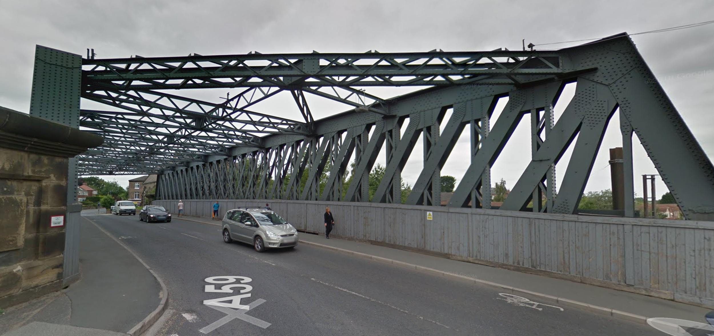
You’ve definitely seen them in the wild. They look like this:

IMG_0733.JPG

Or this: 

IMG_0734.JPG

Or even this: 

IMG_0735.PNG

But engineers prefer to think of them as looking like this: 

IMG_0736.PNG

You see the thing about pin trusses is that they can be shown to follow very simple rules if we pretend they are made of infinitely thin lines, the lines all meet at common points, and every joint occurs at a purely pinned connection (hence the name).

To allow us to talk about the various parts of the truss we have specific names for the main elements. We usually call the horizontal parts booms or chords, and we usually refer to the other parts as the internals, though sometimes we call them the diagonals and verticals depending on their orientation. We call the intersection points nodes.

In pin trusses, as long certain rules are followed the lines themselves never bend; they only experience either compression or tension. What all of those rules are isn’t important for this discussion, but the one about members all meeting at a common pinned node is.

Excellent. We have now described an idealised model of a pin truss made up of line elements connected at pin joints. We know that the truss itself acts like one big element, and in our case that element will be analogous to a beam. And, because I am masquerading as Hercule Poirot I invite you now to imagine me fastidiously straightening the various items on my desk before taking a deep breath and barrelling on.

I’m with you so far, but what does this have to do with connections?

What this has to do with connections is the tension between the ideal and the real.

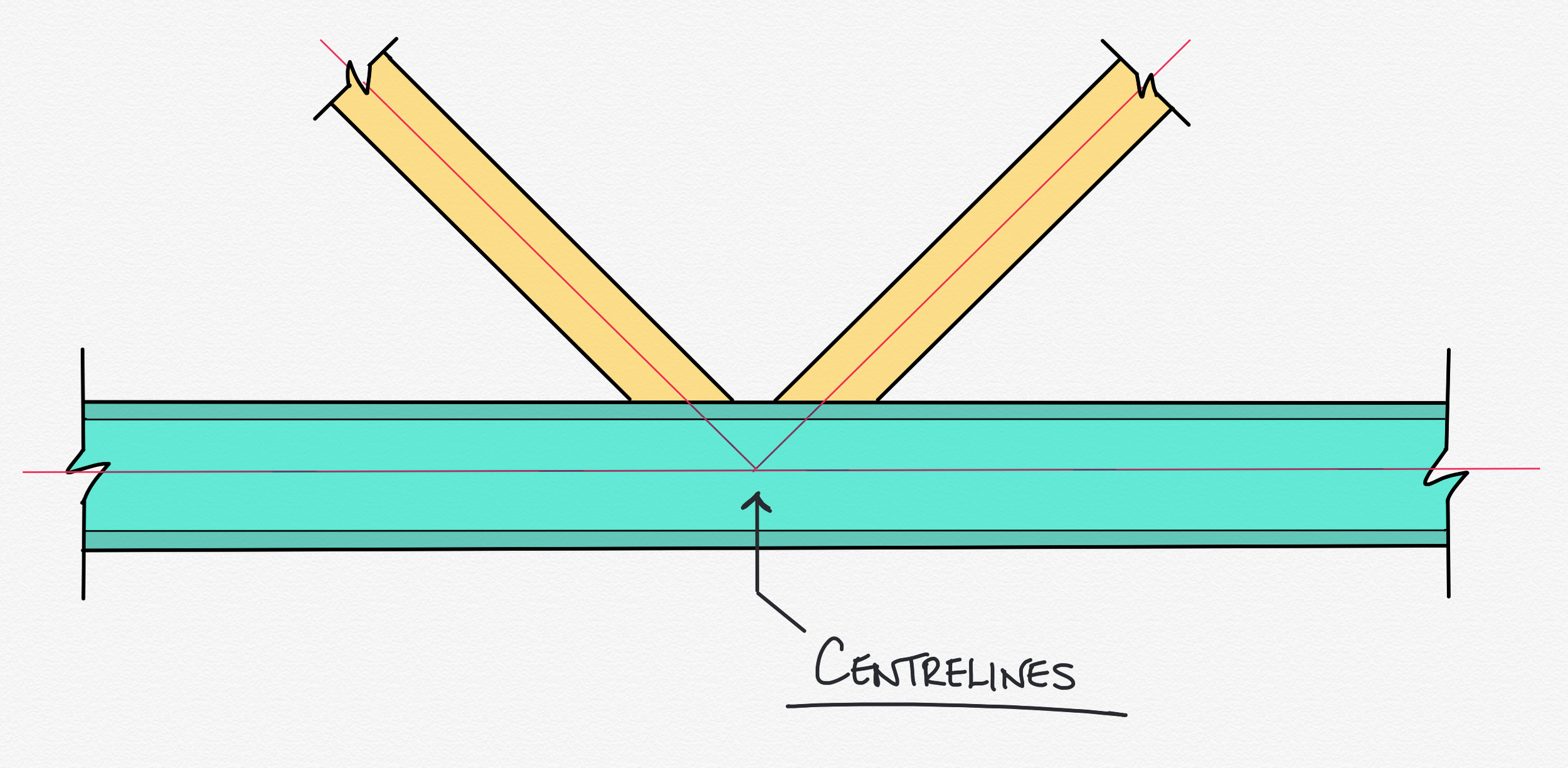
When we draw those infinitely thin lines representing the parts of the truss, we draw them down the centreline of the real lump of metal it represents, like this:

IMG_0737.PNG

Which is fine - we do this all the time. What matters is that it is easy to forget at the design stage that those lines represent something physical; something with shape, volume, and mass.

As per classic Poirot, I’ve sneakily held something back. Something crucial, something that when you look back on it seems so obvious, but often when you’ve had your head in the detail you might forget the bigger picture.

There are rules about how those physical chunks of metal can and cannot be connected. Some of them are simple, common sense rules, and some of them a little more complex, but they are there, they are required, and they are entirely unavoidable. Let’s get on and take a look: the simplest rules to understand from a common sense perspective are the geometric validity rules, and those about member classification.

Rules part one: Geometric validity rules. Specifically, eccentricity 

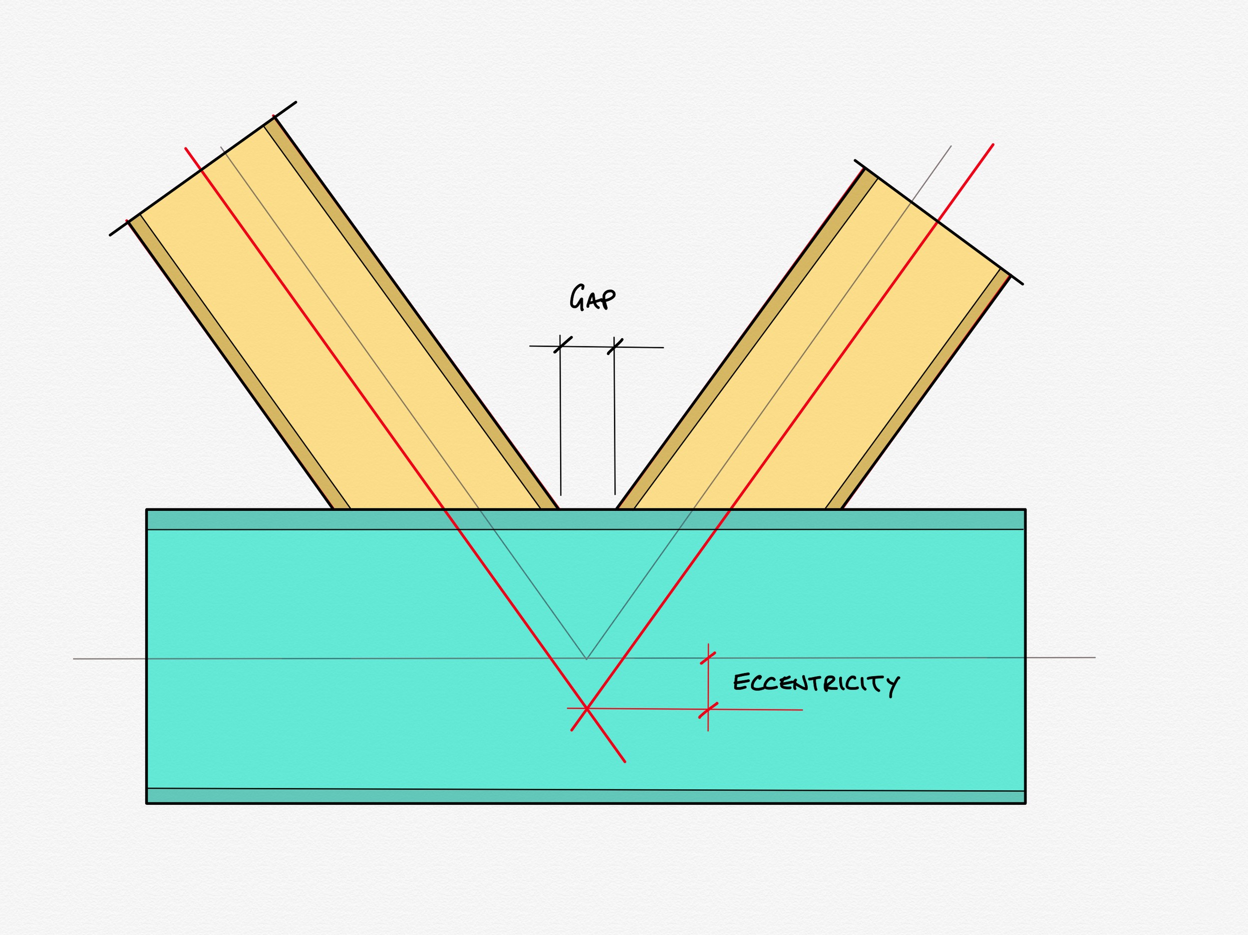
Depending on the size and angle of the diagonals and verticals, rules about maximum or minimum gaps or overlaps between members might end up broken, and things need to be shuffled about slightly to accommodate. The way that you move them to make them valid is usually to move the intersection points of the diagonals away from the nodes. This causes what we call eccentricity - see below:

IMG_0738.PNG

Looks ok? Nothing to worry about? Let’s put some metal on those centreline bones... 

IMG_0739.PNG

Ah. Whilst this might look ok, it is in fact... not. Not only does it fall outside the geometric limits, it is impossible to fabricate, as it requires laying weld on top of weld. We have to alter the geometry to make this valid. 

IMG_0740.PNG

One solution is to pull the node apart like so, creating a decent gap between the noses of the diagonals. Alternatively the members could be overlapped even more, however that is more expensive to fabricate, as it means double cutting one of the diagonals.

Hopefully this starts to ring alarm bells.

If we “un-node” a joint sufficiently, we start to creep away from our idealised model to something a bit more… flimsy.

There a suite of formulae that comprise the CIDECT guide to truss connections which govern exactly how eccentric a connection is allowed to become before it is necessary to take account of the secondary bending induced in the booms, and the overall stiffness of the joints, and the overall stiffness of the whole truss. You can see an extract of the CIDECT guide below showing the validity limits we are forced to work to:

IMG_0741.PNG
IMG_0742.PNG

Here we see demonstrated a common problem: It is extremely rare that a truss is sent to our office that needs no alteration. I can think of only a couple of instances in the last decade or so where I have not had to send alterations like this back for review.

Rules part two: Member classification  

As usual, I’m going to overlook many details and caveats in this next paragraph to avoid layer up on layer of footnote, and to get to the conclusion before I lose you all. Let’s just get going and crash on through regardless.

Member classification is, on a surface level, even easier to understand than noding. Members are broken into 4 classes based on their chunkiness, with Class 1 being the most chunksome, and Class 4 being the most flappy. The rule is that members in hollow section trusses must be either Class 1 or Class 2. Lower class members are deemed to be too flimsy to play nicely. 

This rule is not as often broken as the geometric ones, but it does happen. 

The denouement  

Mes enfants. 

Sorry, couldn’t resist.

Sorry, couldn’t resist.

We arrive here at the denouement. The chapter where Papa Poirot assembles all the suspects, and leads you through the hidden story - the narrative that happened while you weren’t looking. 

We start with the simple question: “who is repsonsible for what?”.

The truss designer is responsible for the overall meta-member itself. If someone other than they were to sabotage the strength of that finished truss, for example to cut pieces out, or to substitute weaker material the designer would be upset, non? Of course they would. They would act to prevent such a thing occurring.

Therefore: 

If the truss designer were to send his truss to be connected up by a third party, and that same third party were forced to make changes that had a detrimental effect on the performance of the final member, the original designer would be equally as troubled, n’est-ce pas?

As it transpires: non. 

Truss designers regularly send their designs out to be fabricated, unaware that those designs are unfinished. They physically cannot be made to the desired specification, and must be altered, and often to some degree of detriment to the truss as whole. Is it right that some third party, completely disconnected from the design requirements of the truss as whole is left to propose alterations? The fabricator will not know nearly enough information to produce a finished holistic design and yet we do

If we recall I started this series talking about a project which actually landed on my desk this year. If you think back to part one, I did in fact mention specifically that the transfer structure of this building was built from trusses, and yes, at least some of these alterations had to be made in that case. Exactly as I laid out above, time was tight, so I proposed alterations that would make the trusses valid and I was also confident the changes would have no detrimental effect on the truss as a whole. The whole exchange was brief, polite and in good spirits as all parties were aware of the time pressures on the job and everyone involved knew this was by far the quickest way to get everything done, and no egos were bruised even slightly.

It does perhaps lead us to the solution of this little mystery. How did we end up here? Are fabricators doing the work of consultants, because we are simply aware that this has become “our area of expertise”  and it’s just quicker if we roll our eyes and do some of their work for them? Is it a slippery slope that we continue to step onto every time a truss lands in our office and we don’t send a stock response of “can you please confirm that all CIDECT validity checks have been carried out? Any reconfiguration will constitute a variation to our works and incur a cost”?

Perhaps. 

I am aware it’s very difficult habit to break. My role as department lead/fictional Belgian detective requires me to react to ever changing circumstance but usually the default position, particularly with trusses, is that the fab shop want the fabrication drawings as early as possible. Trusses are high value items which attract high fabrication hours, so naturally the shop wants them early in the fab programme. If my production director is rightly pressuring my design team to do what they can to resolve truss nodes early to get them into the shop, my best course of action is to do what I can to get the design finished such that we can get them into production. Is this good for everyone involved? Evidently not. I am doing extra work that isn’t mine to do, but on the other hand I am achieveing a more important goal outside of my own narrow ones. Would a firmer stance be better for a fabricator, or would it both slow us down and gain us a reputation for unnecessary belligerence? I’ll end on something very un-Poirot like:

Je ne sais pas.

Responsibilities part two - connections with high tying forces

Continuing on with our investigation into responsibilities in connection design, we will take a quick look at the the first item from our list: connections with high tying forces.

What are tie forces?

Tie forces can best be thought of as OH NO forces. As well as being designed for the expected forces a connection should see in its lifetime, connections on all buildings are also designed for another force, one trying to rip all the bits of it apart caused by something unexpected and catastrophic happening elsewhere in the building. These forces manifest as tension in the connection: acting in a different direction to the forces it must ordinarily resist in its usual operating life, which necessitates some additional checks.

What’s the problem then? Why can’t the fabricator just design for the forces?

The problem comes when tie forces are high. When the tie forces are high, the connection is forced to become chunky and therefore stiff. When a connection is chunky and stiff, it is no longer a pin. You are instructed to design one thing - a pinned connection that can resist the forces required - but the design parameters necessarily force you to provide something else.

I still don’t get what the problem is - so it’s not a pin: why do I care?

The problem is that the chunky connections invalidate the design assumptions of the overall frame design. If the connections aren’t pinned, they are (to some extent) fixed. If they are fixed, they bend the columns, and the columns aren’t designed for this bending*, and could potentially fail. It is the responsibility of the original frame designer to ensure that their design philosophy doesn’t suffer this paradox. To paraphrase David Brown, the frame designer should be aware of the form of their connections, even if they aren’t doing the detailed design of them.

To put it in my own words: A frame designer should have awareness enough to at least eyeball their connection loads against the tables provided in the Green Book. If your loads exceed the tying capacity for the standard connections, you know that you are in the realms of bespoke connection design and ought to be doing two things:

  1. Checking your columns for extra bending

  2. Providing a note on your GA drawings to say that bespoke connections are expected, and that the connections provided need not be strictly pinned.

*Note - the columns are in fact designed for a good deal of bending. The bending induced by over-stiff connections is in addition to this and can potentially over-stress the column, leading to yielding or buckling failure.

How was it resolved in our real-world project?

Having got the theory out of the way - where did this leave us on project? Our project was littered with connections falling into this category: in fact more connections than not were of this variety.

I would love to tell you a tale of the resolution of this conflict as an epic battle of one team’s collective wit pitted against another; a competition in which only one team would be able to hold their heads high after, where the loser was condemned to wander the streets with their faces buried shamefully in their hands, but it would be a complete fabrication (groan).

In truth, when we received the loads for the connections, the consultant and I had the briefest of polite conversations in which I told him that just by glancing at the magnitude of the loads I could tell that many of his connections on this job would not be able to classed as strictly pinned, and would he kindly check his columns out for some additional bending. He swiftly replied that he was perfectly content without needing to check his model, because he knew that he’d massively over-designed the columns in the first place.

Responsibilities in Connection Design

Today I want to pull together a couple of threads which have been brought to mind by events which occurred a few weeks ago. I will do my best to keep the language layperson-friendly, and as such will no doubt butcher some (ok, many) structural concepts.

I have been planning since the very beginning of this blog to pick apart some of the tricky areas of overlap in design responsibilities between fabricators and consultants, and a project I have just completed design work on nicely highlights a good few of these tricky areas.

My company recently won a traditional contract with a very short lead-in. The contract was to supply a multi-storey building with a significant transfer structure* consisting of a system of trusses which in turn carry two columns from first floor right up to the roof some five storeys up. We were given just ten weeks from the point of order to requiring the first loads of steel to be erected on site. This is about six weeks short of the period we’d usually have: time was tight, and this project was complex.

*Transfer Structure: A term usually given to typically heavy-duty structure used to carry other structural elements. In this example there is a large lecture theatre on the ground floor which cannot have columns in the middle of it. In our case above the lecture theatre, hidden in the ceiling, are enormous trusses which have the columns for the rest of the building above resting on them. The trusses transfer the load from the carried columns out to the columns on the perimeter.

The David Brown

Those of you diligent engineers who fastidiously carve out time to read The Structural Engineer every month will of course have read, digested, reflected upon, and taken to heart all the advice given in this wonderful article written by David Brown of the Steel Construction Institute in their July/August 2016 issue. For those of you have haven’t already, you’re about to get a sub-standard re-hashing of great swathes of it, but presented from the figurative coal (steel?) face. I highly recommend reading Brown’s article if you are an engineer who has ever designed steel framed buildings whilst working in consultancy. Or a human being interested in reading this website for that matter.

Brown’s article has six sections, covering the following circumstances:

1. Connections with high tying forces.

2. Flange to web welds in a plate girder.

3. Joint resistance in hollow section trusses.

4. Holding down bolts and foundation design.

5. Nominally pinned connection invalidate the original assumption of full fixity to the column.

6. High shear and bending.

If any of those terms in the section titles cause you to scratch your head; fear not. We’ll be explaining as we go along.

This project had instances of four out of the six situations covered by Brown’s article: connections with high tying forces, joint resistance in hollow section trusses, holding down bolts with significant shears and uplifts, and high shear and bending. In the following series of articles here, I’ll cover each in turn, explaining what they are, and how each was resolved.

To round out this introduction, I’ll give a brief explanation of the two circumstances not present on our example contract.

Flange to web welds in a plate girder

Of all the sections in Brown’s original piece, this is by far the shortest (just 23 well chosen words). A plate girder is beam or column not rolled as a single lump (imagine rolled sections coming out of a very hot, and very large sausage machine); instead a plate girder is made out of three flat plates which are later welded together into an I or H shape by man or machine.

The conflict between consultant and fabricator is over which of the parties designs the welds between the plates - that is the welds that hold the beam together. I don’t know how conflict over this responsibility ever became common: the line is clear. The person who designs the beam designs those welds: they are not connection design, they are integral to member design.

In terms of my own experience, it is common for consultants to deem this as part of a fabricator’s remit, and without fail we send it back to the consultant, occasionally with a link to Brown’s article.

Nominally pinned connection invalidate the original assumption of full fixity to the column.

That’s a bit of a mouthful isn’t it? Breaking it down, it’s not that hard to get your head round. This comes down to assumptions made (perhaps unknowingly) at frame design stage that aren’t passed on at connection design stage.

When designing columns, engineers can “pretend” that the designed length of a given column is a small amount shorter than its true length to take account of how free bits of it are to rotate. This means you can justify a lighter, cheaper column size. If the column is really well “grabbed” at the floors of a building by the incoming beams and the concrete floor, it can’t buckle there and will start to buckle slightly away from the floor rather than right at it.

Problem is, that if an engineer is using these methods, they need to be satisfied that the connections done by the fabricator are rigid enough to justify their original assumptions. I’ve been doing this job 10 years now and I have /never/ been told that my connections are to be robust enough to justify a shortened column effective length. How many of those buildings have used a reduced column effective length? I have no way of knowing, but I would put good money on the number being non-zero. I’ve said this didn’t occur on this building, but now I come to write this, I realise I can’t actually be sure.

Next time

Next time, we’ll dig into the specifics of the connections and responsibilities of the real job we won with the short lead in. First up: connections with high tying forces.

Boring myself: or let’s make this snappier.

You know what? Over the last few weeks I have written 1500 words about pinned connections and did a boatload of sketches to go with them, but every time I came back to do an edit pass I was bored. I’m not trying to write a dry textbook; I’m trying to write about my industry with enthusiasm and, one would hope, a little insight.

I reckon it’s time to kill this particular darling and just pull out the few interesting bits that were peppered in with the dross. Starting today I’m going to try to bash out a short little snippet every day or so to get this thing back rolling again.

Let’s do this. 

Pleasant Interlude No. 1 - Procreate 4.1

A quick post for a good reason. The makers of the iOS painting app Procreate have made their roughly annual update, and two of the less heralded features turned out to be complete game changers for my sketching at work, and therefore my illustrating here.

Up until now I’ve made many a mention of Linea Sketch, which thus far has been my go-to sketching app, but now I am afraid that the King is dead. Long live the King.

I’ve been using Procreate ever since getting my iPad Pro and Apple Pencil, mostly for portraiture (let’s not go there for now, but suffice it to say that even engineers-cum-bloggers need a hobby) but never considered it for the quick and technical sketches I need to produce here mostly because it was just too much. It was the metaphorical sledgehammer to crack the walnut. Essentially Procreate is a tablet-first boiled down version of Adobe Photoshop, and even when using Procreate I barely scratch the surface of its feature set. For a feel for what Procreate is able to do in the right hands, check out their showcase.

Now as I said the newest version, Procreate 4.1, has some snazzy new features that have pushed it from an also-ran in my sketching toolbox to uncontested king of the hill. Those features are the improved quicklines and the expanded assisted drawing.

Previous versions of Procreate have had both of these features, but now they have developed beyond their previous capabilities into must-have features for technical sketching.

Quicklines have been a part of Procreate as far back as I can recall, and they work in almost precisely the same way as Linea’s ziplines - essentially you define a start point of a straight line, then place the end point. The effect of the update is that now once a quickline has been laid down editing handles appear offering the user an opportunity to move either end or the whole line before it becomes baked into the image. As a surprise added bonus, the appearance of the edit handles is an event in the undo/redo stack, so if you accidentally tap off and ‘bake in’ your quickline unintentionally, double tapping to undo brings back your edit handles, allowing the user to re-edit position again rather than having to redraw the line from scratch.

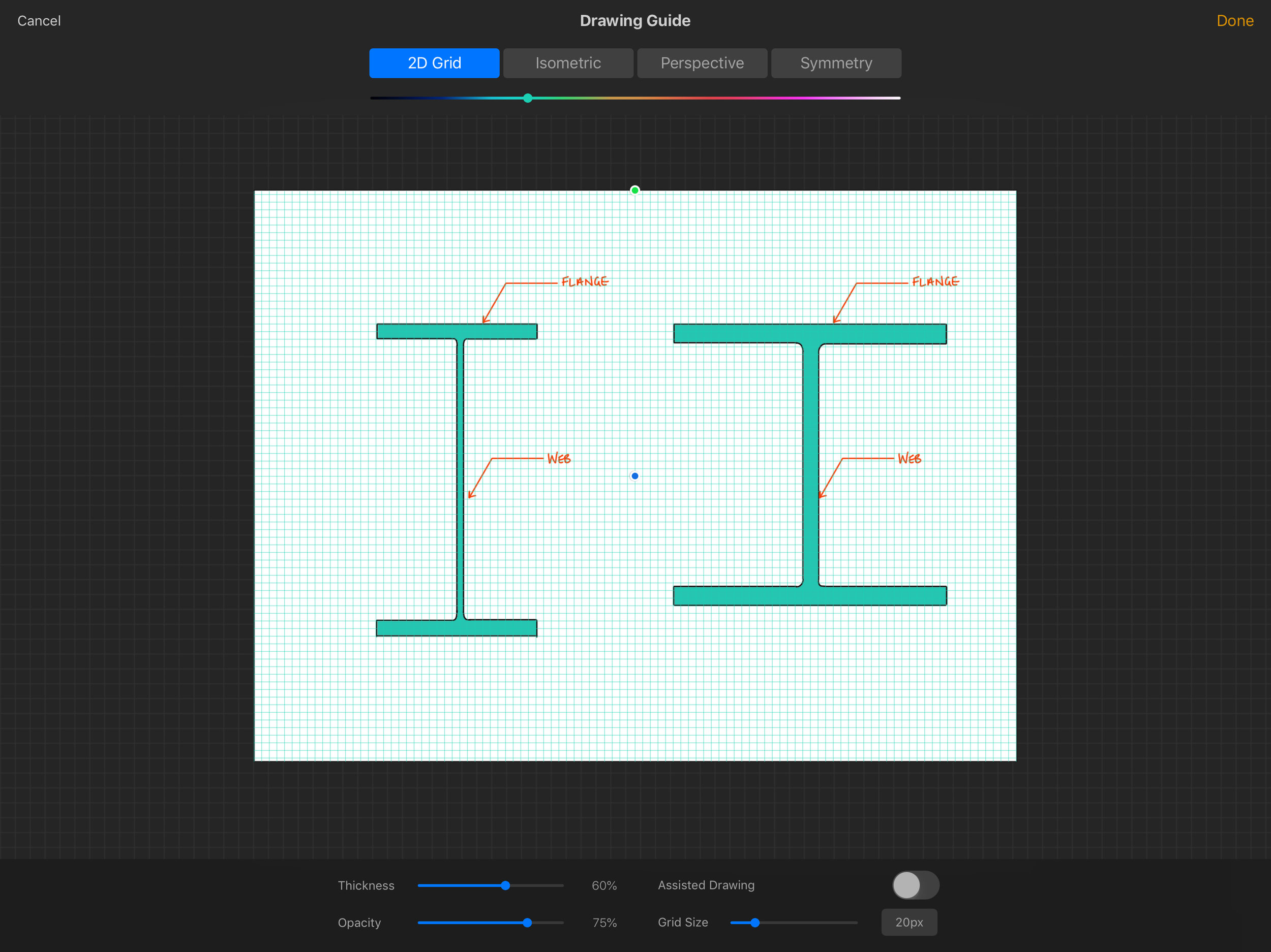
Assisted drawing was also a previous feature that was initially only for perspective drawing. You defined one, two or three vanishing points to generate guidelines and with the flick of a switch Procreate would force all lines drawn to conform to your guidelines. The 4.1 update includes 3 new modes of assisted drawing: isometric, orthogonal, and symmetry lines. The orthogonal guidelines force all freehand lines drawn to be either horizontal or vertical, but in a stroke of utter genius quicklines can still be defined at any angle even when assisted drawing is toggled on. In other words, Procreate 4.1 can be used almost analogously to a traditional drawing board. You have the equivalent of a set straight edge and a set square with 15 degree increments*, plus the ability to put down a straight line at any arbitrary angle for constructions.

In summary, Procreate 4.1 has leap-frogged all my iPad competition for dock space and is now unquestionably the One True Sketching App for all my needs. All linework can be laid down in no time at all, the interface is quick and breezy, and there is a pleasant fill tool with adjustable threshold. The likelihood is that for the foreseeable future, all my illustrations here will be done in Procreate.

A little WIP shot. The gridlines do not show up in final images.

A little WIP shot. The gridlines do not show up in final images.

*achieved via a Quickline gesture. Super useful.

Paperless Working Part 1 - GoodNotes

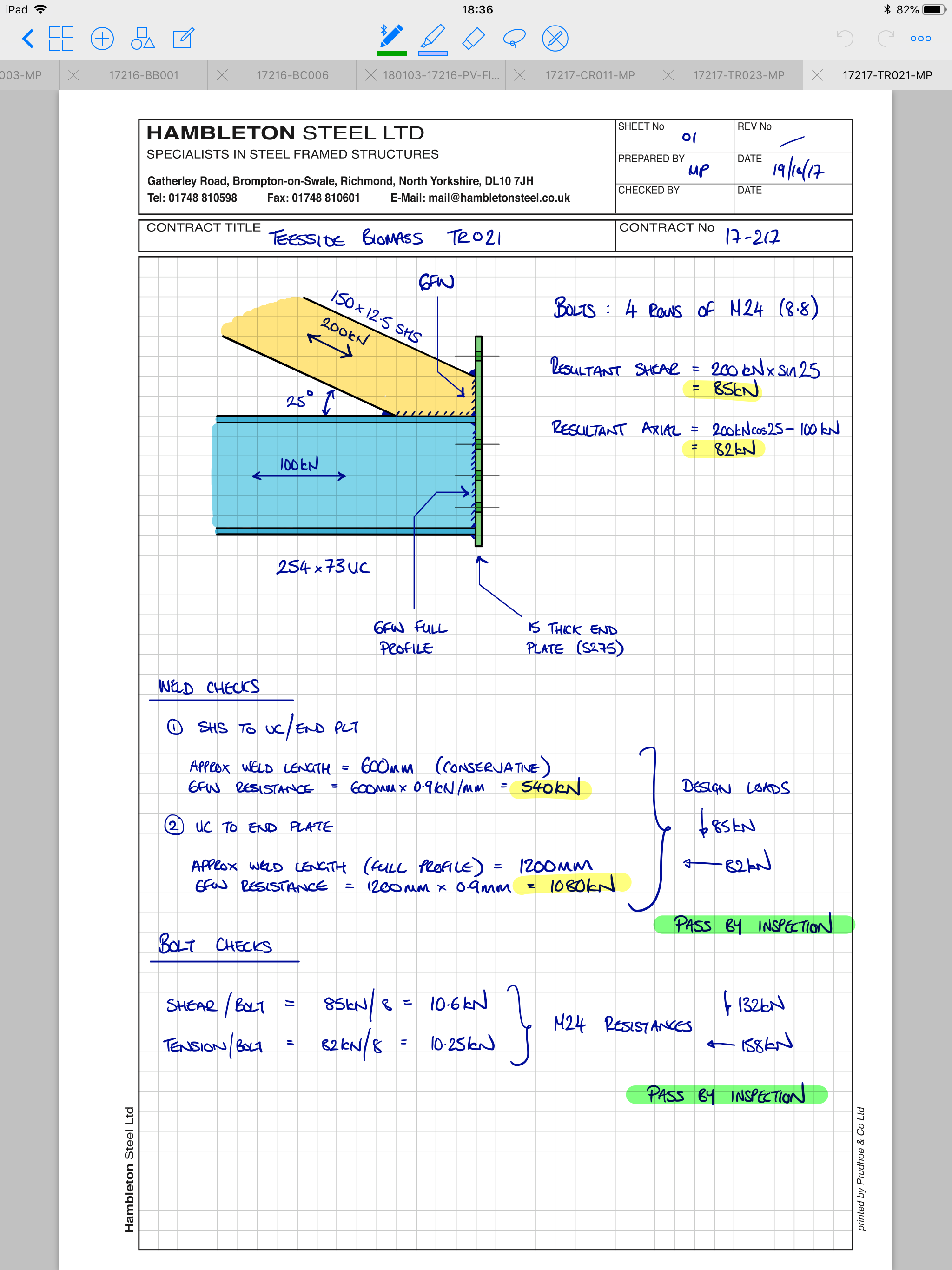
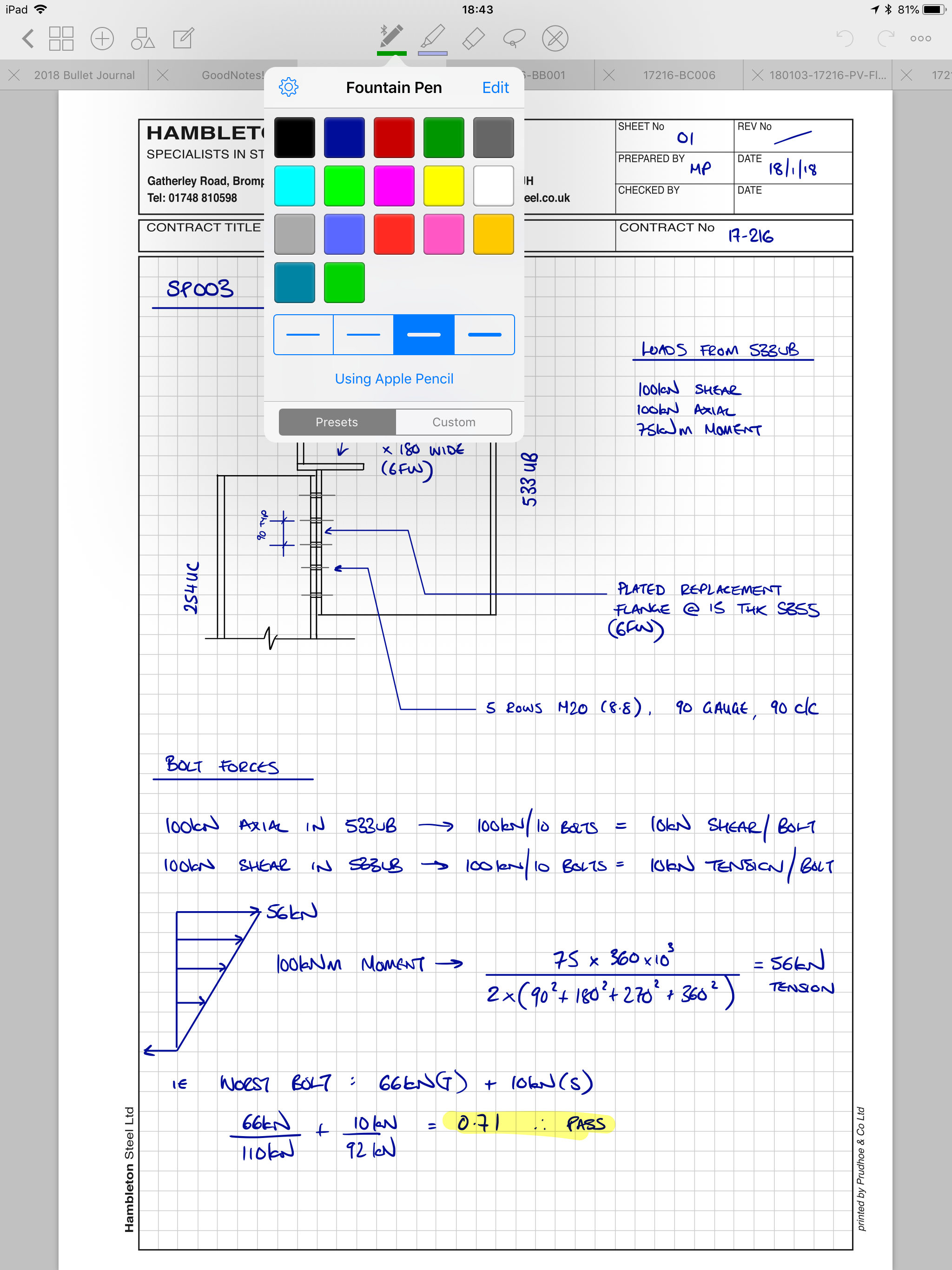
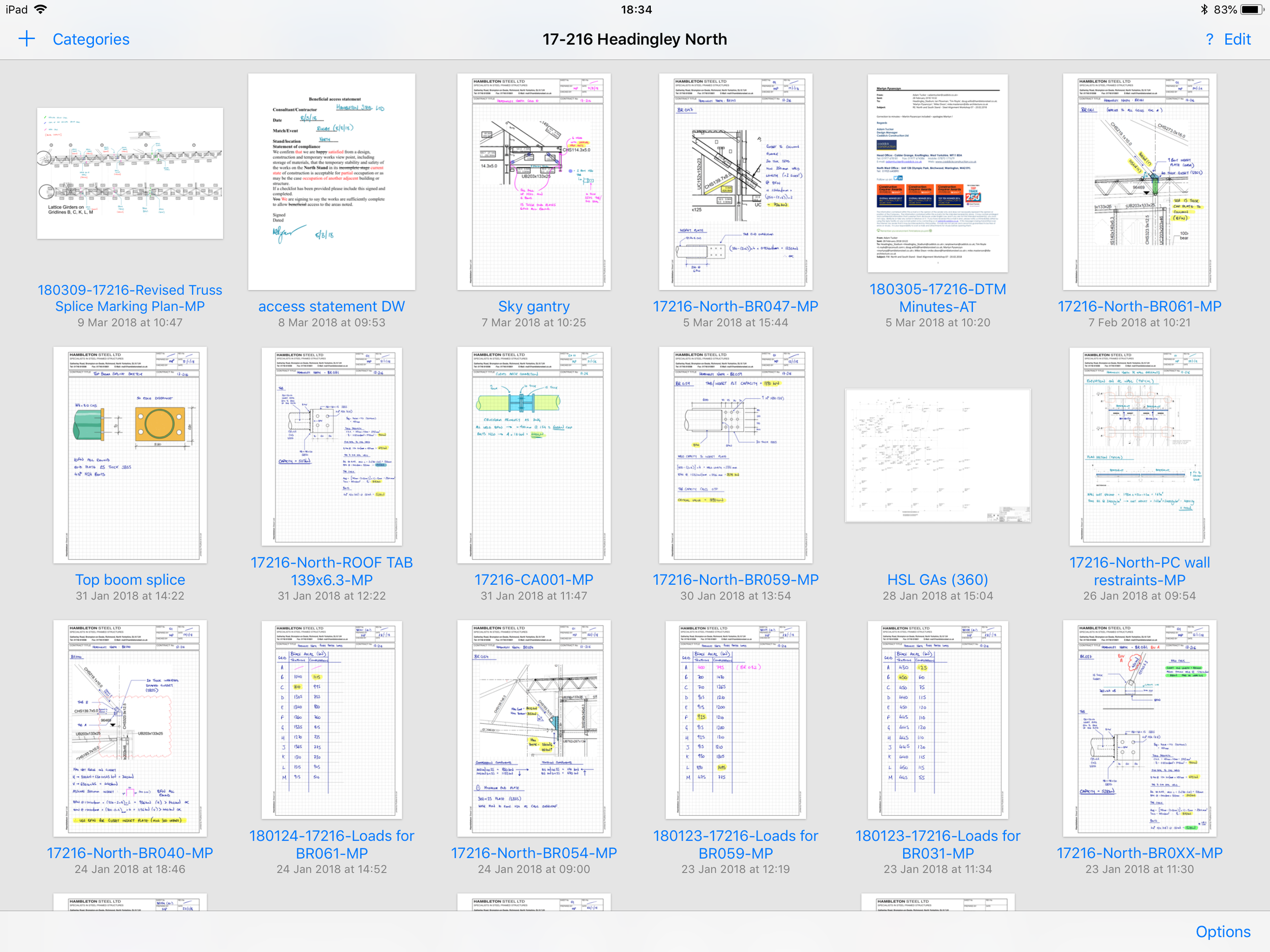
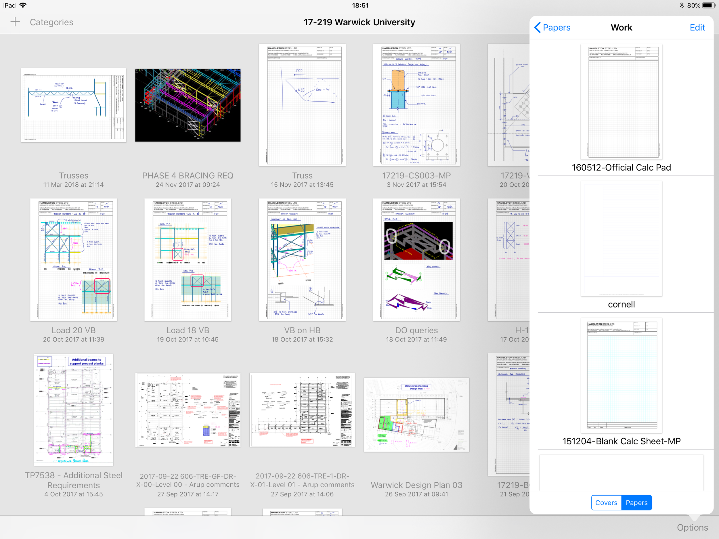
If you were to take a look at my iPad when I’m working I can safely estimate a 90% chance you’d see it running GoodNotes. Everything I would have previously done on paper, is now done on my iPad Pro 12.9” via GoodNotes with the Apple Pencil.

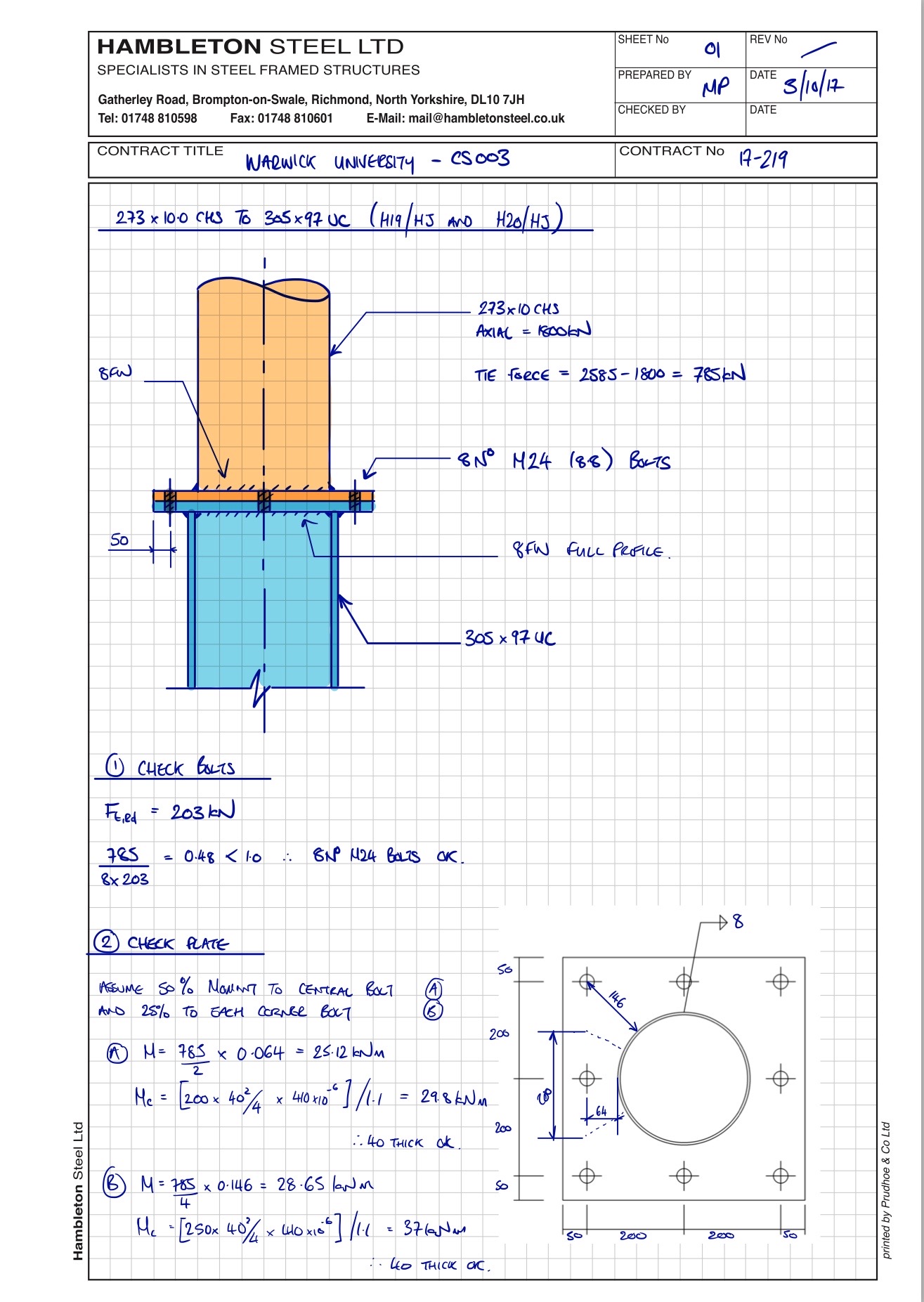
  • Hand calculations: GoodNotes
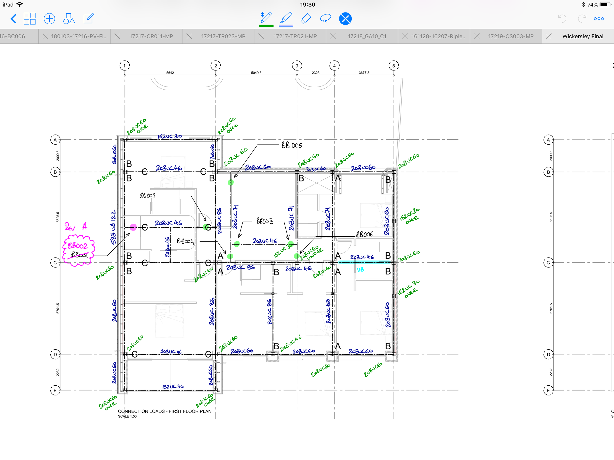
  • Marking up drawings: GoodNotes
  • Any sort of document that requires my signature: GoodNotes
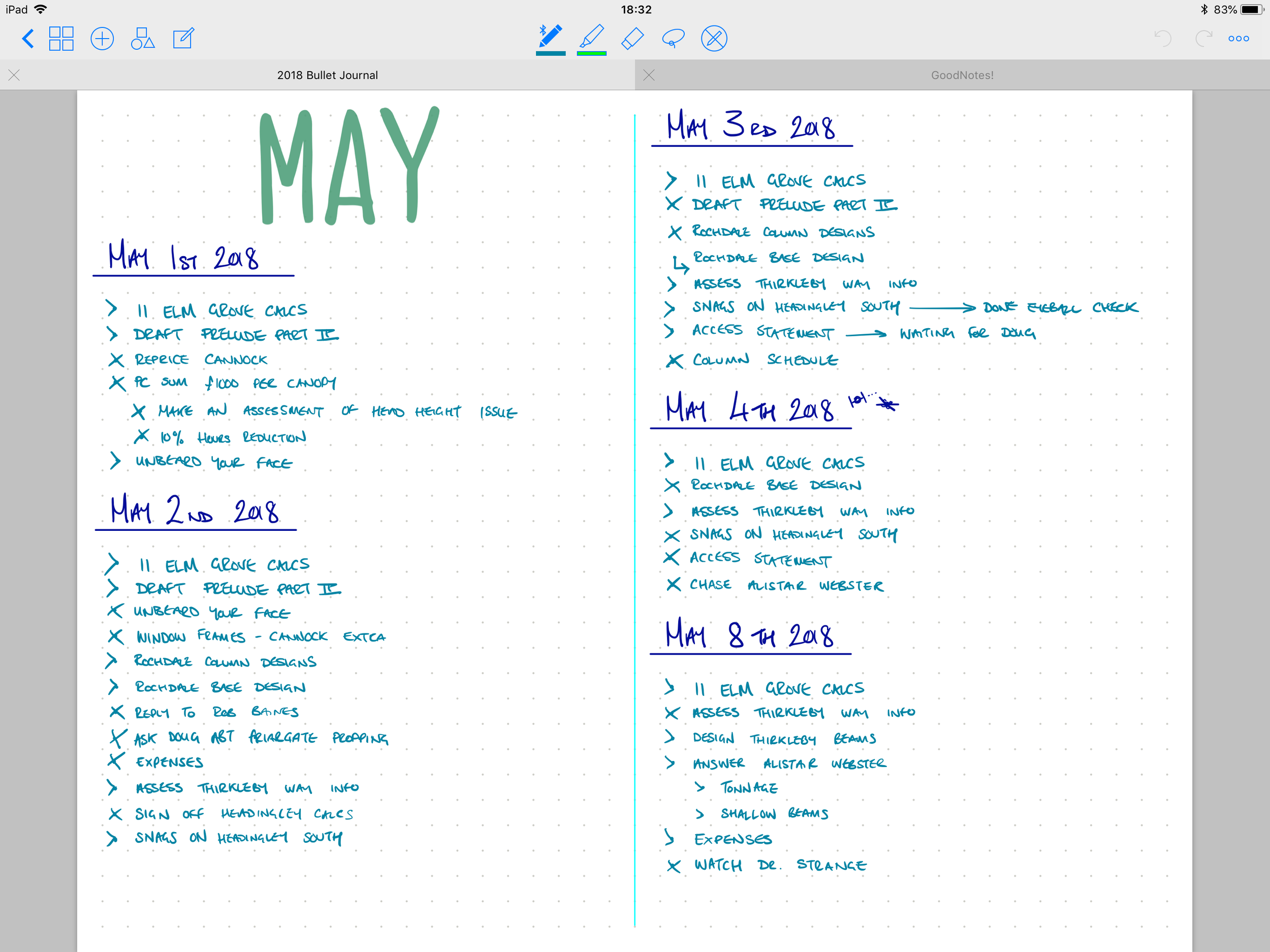
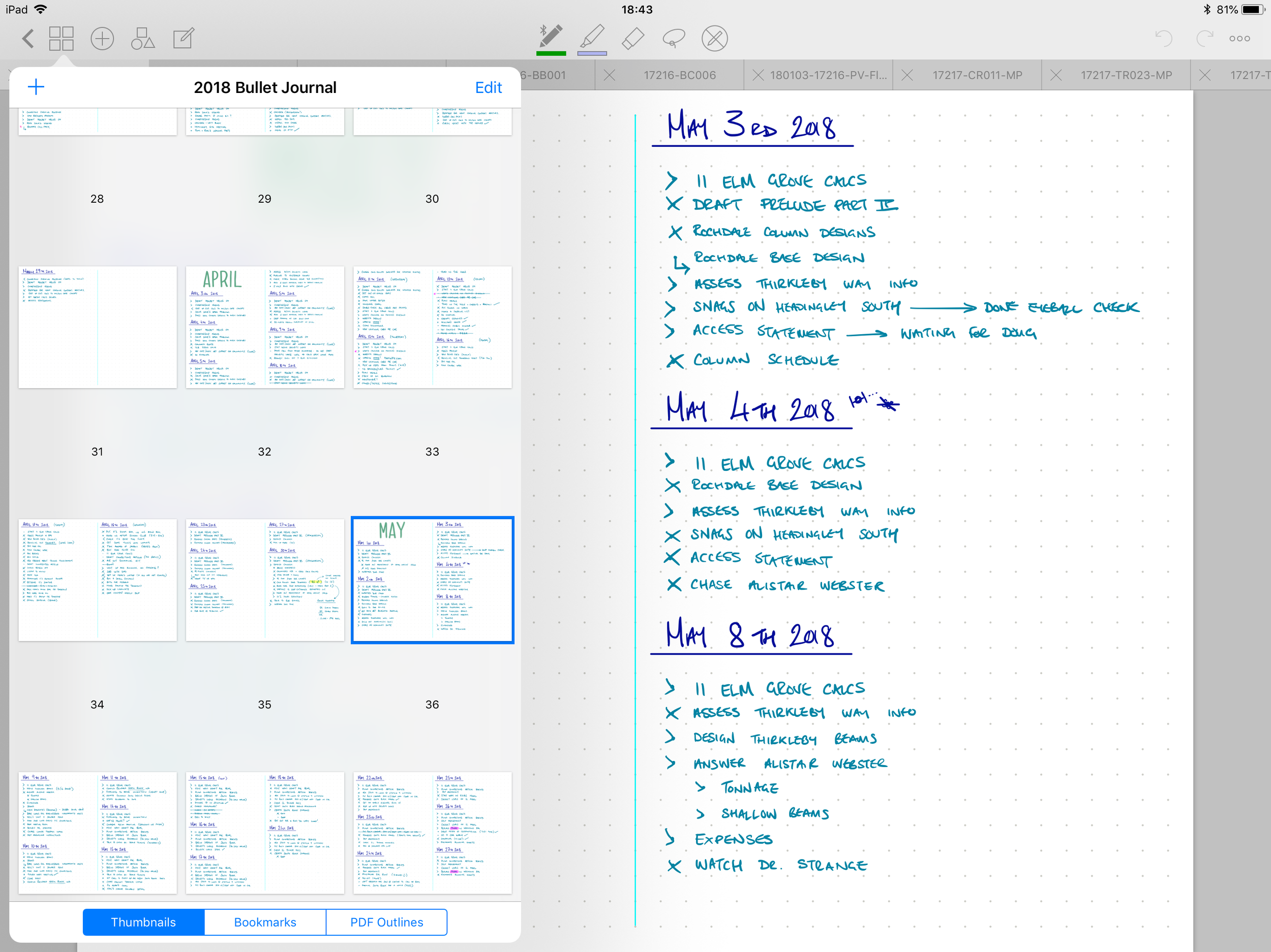
  • To-do list: GoodNotes
  • Specification documents needing to be reviewed: GoodNotes

Note: clicking on an image in the gallery moves to the next image.

And the list goes on. 

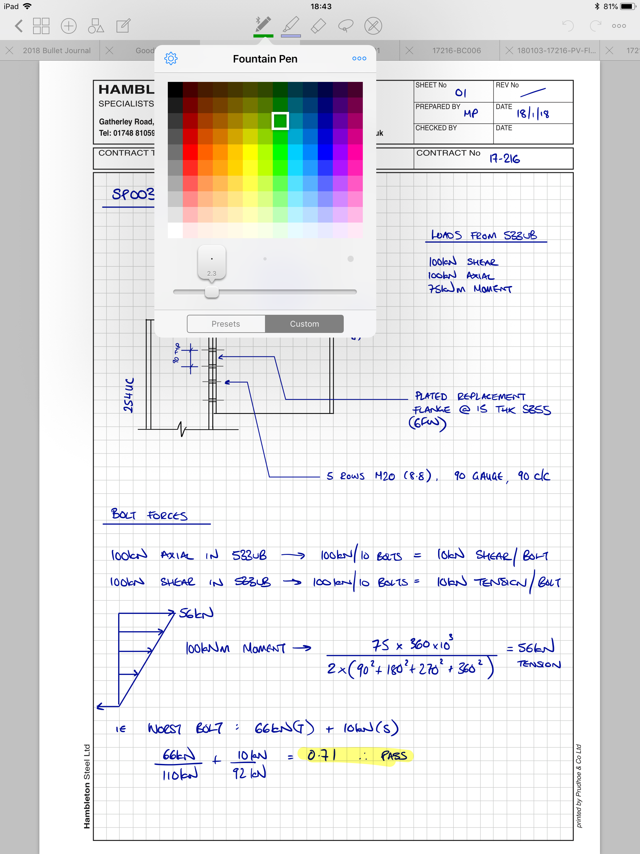
GoodNotes is at its core a vector based PDF markup tool with a small but near perfect box of tools. The most notable feature is the very best digital handwriting inking engine I’ve seen on iOS - and I have tried a lot of handwriting apps. The talented people who made and maintain GoodNotes market it heavily to students as a note-taking tool, and with good reason - it is truly wonderful for note-taking. The great news for engineers is that the features included and the design decisions made for GoodNotes make it an incredible paper replacement for the practicing structural engineer.

Before we talk about why GoodNotes is great for engineers, let’s cover the basics: Any handwriting app worthy of notice should feel great to write on, and produce handwriting that is unmistakably that of the writer. GoodNotes does this splendidly. The act of writing feels natural, and the results, at least to my eye, are perfect. Also notable: the palm rejection with the Apple Pencil is great.

The pen tool can be switched from a fountain pen feel to a ball-point pen feel, and there are 15 preset colours to choose from. You have the option of expanding your default palette from a grid of 150-odd more, or the freedom to feed it hex codes for any colour you wish. There are 4 preset stroke widths to pick with, but they can also be adjusted with a custom slider. I’ve tweaked my stroke widths slightly and added two shades of green to my palette, but otherwise tend to stick to the defaults. My go-to colours in the fountain pen are the default deep blue, and a teal that I took from the expanded colour picker.

The highlighter tool has the same colour and stroke width customisability, and the transparency allows you to layer colours up too, should that take your fancy.

Aside from the excellent pen, there are tonnes of features that make GoodNotes ideal for engineers. You can:

  • Import PDFs as templates into the app’s library. This is where I keep a copy of our company’s calc paper. New page creation is an absolute doddle when you are working too. To create a new blank page, you simply swipe past your final page and GoodNotes will insert a new page using the template you’re currently working on.
  • Import PDFs as standalone documents (from Dropbox or similar), or import them as new pages in an existing document. Want to import a set of architect’s drawings? No problem - you can decide either to import them as individual files (which you can view in separate tabs), or you can import them a single batch so each drawing is in one multi-page document with each drawing on a separate page.
  • Draw straight lines and a few basic shapes with either the pen tool or the highlighter tool with a toggle. This is extremely useful for doing small sketches within your calcs, or neat dimension lines or leaders.
  • Use a lasso tool to select and move or copy any marks you’ve made. This is very helpful for sketches, and little things like copying titles across calc pages as well as just making everything line up nicely after you’ve done it. The lasso can be toggled to select any or all of handwriting marks, imported images, and text boxes. This is such a useful touch - if you’ve imported a snapshot of a drawing or design model and marked it up you can still tweak your marks without also moving the import underneath. 
  • Search within your notes for text including your handwritten notes. The OCR is pretty damn accurate.
  • Insert images and text, rearrange your pages and all the other myriad basics you’d expect. Especially handy is support for transparent PNG files, which allows seamless import of more complex sketches done in other apps. 
  • Switch the eraser tool from traditional to erase entire stroke. This is incredibly useful for correcting dense calcs. Also very handy if you want to draw some guidelines for writing, then erase them after.
  • iCloud sync means that everything on my iPad is also available on my phone. I personally don’t use the phone version for creating anything, but having access to absolutely everything I’ve ever written all of the time in my pocket has saved me on a good few occasions. 

Before I wrap up, it’s only fair I mention the few things that could be improved, particularly from the point of view of an engineer. I realise my wish list is both rather selfish and not necessarily aimed at the core market of the app, but I’d like to hope that improvements that fix the issues I have highlighted below will benefit all users... So, here goes:

  • Selected items cannot be scaled or rotated. This is a feature available in GoodNotes’ closest competitor, Notability, and I suspect is one the developers are actively working on. 
  • Whilst realising GoodNotes is a handwriting app first and foremost, the limitations placed on sketching are sometimes a drawback. For example, the straight line detection will snap lines drawn at shallow angles to be horizontal. A ruler tool like the one included in the Apple Notes app would be wonderful. Better yet if it could at least report the angle to the horizontal and better still if the user could define an angle to set it at.
  • If I’m being really cheeky, a straight up copy of Adobe Sketch’s French Curve tool would be lovely.
  • GoodNotes lacks a fill tool. A good deal of my time when sketching in GoodNotes is spent oh-so-carefully trying to use a highlighter with a circular tip filling in shapes with defined square edges without going over the lines OR taking the pencil off the screen. If you do either you have to start again if you want a neat block of uniform colour.
  • Bookmarks added to GoodNotes do not export back out to PDF. I believe this is also on the to-do list of the developers though.
  • Really getting nitpicky now: the default action when importing multiple items is to import them all as separate documents within GoodNotes. Getting them into a single document is a manual if fairly quick and simple process, but it would be lovely if the app were to ask if you want one document or multiple at point of import.

To summarise:

For the practicing engineer GoodNotes has almost everything you need to replace paper. Since getting my iPad Pro and GoodNotes about a 2 years ago I have not used a single sheet of calc paper. I still hop out of GoodNotes to create complex sketches in either Linea Sketch or Paper by 53 depending on the style I’m going for. Both of these apps are able to export transparent PNGs to import back into GoodNotes, blending them seamlessly into your calcs.

Given that GoodNotes is primarily a note-taking app, I can absolutely forgive it for not catering to my entire fantasy wishlist of features, and declare it truly and honestly to be the number one app on my iPad, head and shoulders above everything else.

GoodNotes, I salute you.

Connections: the basics

This is to be the first in a series of articles, where the aim is to introduce the different types of steelwork connections, when the various types should be used, and what ought to be considered in their application. I am by no means an expert in the field but I have 10 years of experience in designing connections, both for buildings I have designed myself and for buildings designed by others, so hopefully my advice is practical and useful if not necessarily academic.

I hope that this series will prompt engineers designing steel structures to consider how their selection of members constrains connection design, I hope it will aid connection designers from making avoidable elementary mistakes which, for example may cause members to be impossible to erect. I also harbour a deep hope that this series is at least informative and ideally at least a little bit interesting.

Steel to steel connections can broadly be split into two main categories: those which allow rotation, and those which do not. We call the former pinned connections and the latter moment connections.

Let’s start our brief overview on familiar territory; pins.

Pinned connections

At the end of our pair of prelude articles, we had defined what a pin connection is and how one behaves. Broadly speaking, pinned connections are typically used in the following circumstances:

Beam to beam, and beam to column connections

By far the two most common types of pinned connection are the first two - beam to beam, and beam to column, and as luck would have it, both work in almost precisely the same way.

bb-bc pins.png

Column to column connections (hereafter column splices)

Column splices are, even by the standards of a series of technical articles regarding steel connections, fairly dull. They come in two broad flavours, which I’ll cover at a surface level, and that’s about your lot.

col spl.png

Bracing connections

Bracing connections on the other hand are both varied and interesting. They take many forms and are often the most crucial connections in a structure. Correctly designing your bracing system is critical, thus ensuring the connections can transfer the loads as intended is equally critical.

bracing.png

Truss Connections

Truss connections are a fascinating topic to me as much because of the politics surrounding who actually designs them and at what stage in the design process as due to their inherent variability and complexity.

Truss.png

Moment connections

Moment connections, or moment resisting connections are effectively the opposite of pinned connections: they are designed to be rigid, i.e. they resist rotation. They come in all the same flavours as the pinned connections above, except for bracing connections. This is because braces should never bend, therefore their end connections should never need to be designed to resist bending.

Beam to column moment connections

These are probably the most common kind of moment connection by a hair. They come in a few main varieties, but by and large are fairly straightforward.

haunch.png

Beam to beam moment connections

These tend to follow the form of our column splices from the pinned category. As such, they aren’t massively varied, but nevertheless worth a short article on.

beam splice.png

Column splices

Much like their pinned counterparts. In fact so much so it’s likely I’ll cover both pinned and moment resisting in one article.

col spl.png

Truss connections

Moment resisting connections are rare in trusses - they only tend to appear in a specific type of truss called a Vierendeel truss, which is itself essentially a rigid ladder frame. The connections are straightforward beam to column type affairs, but the trusses themselves and the likely restrictions on connections are worth covering.

vierendeel.png

What next?

Having covered a lightning round of all the basics, I suppose it’s best to dive right in and begin at the beginning. Next time, we start on pinned beam to beam and beam to column connections.

As always, comments or corrections welcome at @martynpie on Twitter, or by email on martyn@martynpie.com.

All today's sketches drawn in Paper by 53.